
Motorized scaffold with displaceable worker support platform

a technology of displaceable platform and motorized scaffold, which is applied in the direction of building scaffolds, lifting devices, structural elements, etc., can solve the problems of motorized scaffolds, difficult to position them in restraint spaces, and fairly heavy and bulky apparatus, so as to achieve safe and efficient manner

Inactive Publication Date: 2006-02-28
FREDETTE JEAN PAUL
View PDF11 Cites 39 Cited by
  • Summary
  • Abstract
  • Description
  • Claims
  • Application Information

AI Technical Summary

Benefits of technology

Enables efficient and stable operation on diverse terrains, allowing workers to access large areas without relocating the scaffold, providing stability and safety for workers and equipment, and facilitating work in tight spaces and uneven environments.

Problems solved by technology

There are several problems associated with known motorized scaffolds as such are fairly heavy and bulky apparatus.
Accordingly, with these known scaffolds it is difficult to position them in restrained spaces and they are primarily limited for use adjacent to large building structures that are easily accessible.
Also, most of these scaffolds are supported on wheels and therefore due to its heavy load they are not practical for use on soft, muddy terrain.
Such a structure is also unstable if large working materials were to be placed at one end of the working platform making the platform imbalanced.
Furthermore, such motorized lifting apparatus is not feasible for working in narrow restrained areas between buildings if such areas are narrower than the width of the platform and support vehicle.
Still further, with these prior art scaffolds it is necessary to displace the scaffold each time work is completed adjacent the scaffold as these are not laterally extendable.

Method used


Image

  • Motorized scaffold with displaceable worker support platform
  • Motorized scaffold with displaceable worker support platform
  • Motorized scaffold with displaceable worker support platform

Examples


Embodiment Construction

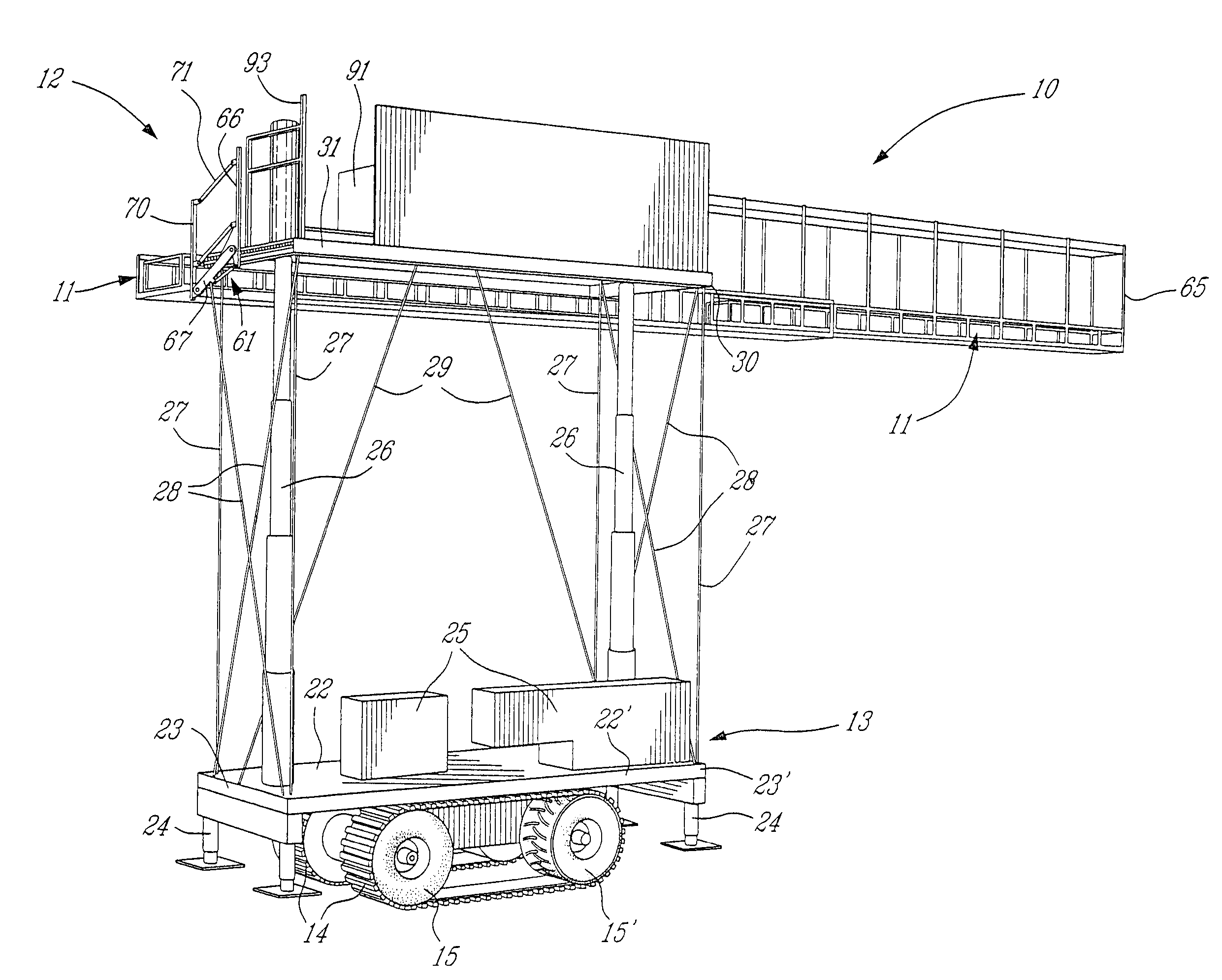
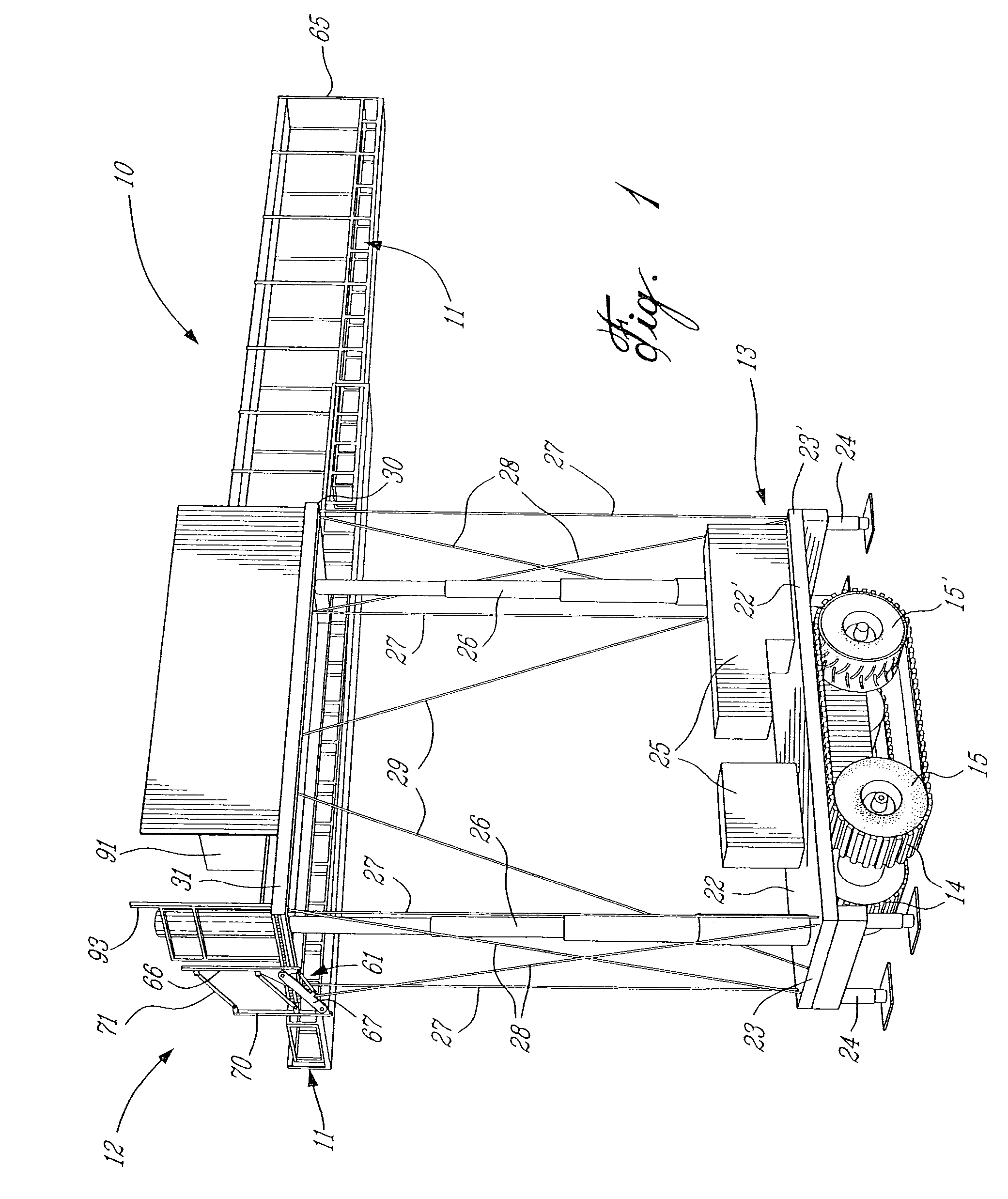
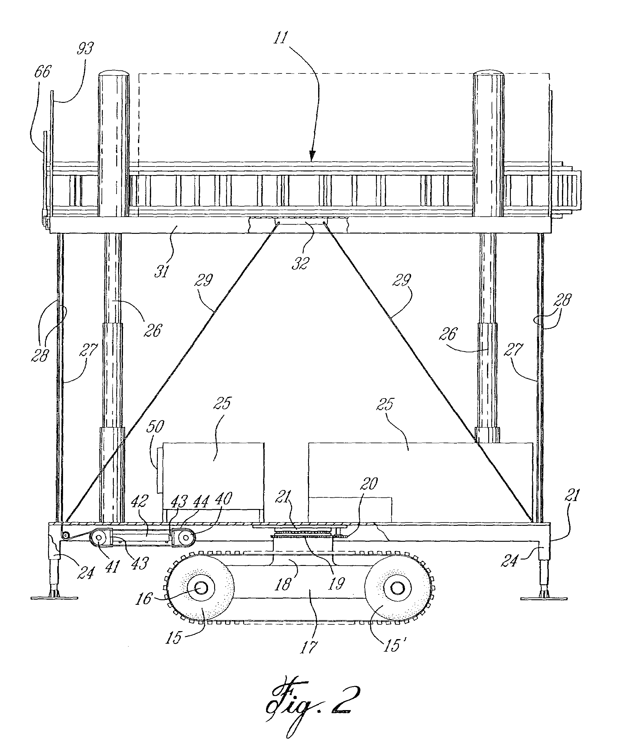
[0027]Referring now to the drawings and more particularly to FIG. 1 there is showing generally at 10 the motorized scaffold of the present invention and which is equipped with a displaceable worker support platform 11. The worker support platform 11 forms part of a platform assembly 12 which is displaceably secured to a motorized support base 13. The motorized support base is provided with traction means in the form of a pair of ground engaging endless traction belts 14 each of which is trained between and about the pair of wheels 15 provided with traction tires 15′ on opposed sides of the base 13. As shown in FIG. 2 the wheels 15 are secured to respective axels 16 mounted on an undercarriage 17 which is secured to a large pinion 18 provided with a circumferential gear 19. A pinion gear 20 is motor driven whereby to displace the undercarriage 17 and its wheels 15 on a pivot connection 21. Accordingly, the undercarriage 17 can pivot 360 degrees with respect to the support base 13 whe...


PUM


Abstract

A motorized scaffold for self-displacement on land is comprised of a support base mounted on a pair of traction belts. Jacks are provided to immobilize and level the support base at a desired location. A platform assembly is secured over the support base on extendable supports. Braces are secured between the support base and the platform assembly and are extendable with the movement of the platform assembly over the base whereby to maintain the platform assembly substantially stable during its displacement and at a stationary desired working elevation with respect to the support base. A displaceable worker support platform is secured to the platform assembly for supporting workers thereon.

Description

TECHNICAL FIELD[0001]The present invention relates to a motorized scaffold with a displaceable platform assembly having a telescoping support platform and wherein displaceable bracing cables are provided to maintain the platform assembly substantially stable during its displacement and when at a stationary desired working elevation.BACKGROUND ART[0002]Motorized scaffolds are known in the art and such is exemplified, for example, by U.S. Pat. Nos. 3,785,454 and 6,349,793. There are several problems associated with known motorized scaffolds as such are fairly heavy and bulky apparatus. Accordingly, with these known scaffolds it is difficult to position them in restrained spaces and they are primarily limited for use adjacent to large building structures that are easily accessible. They are not made for displacement on irregular terrain as we find on construction sites where the terrain is not level. Also, most of these scaffolds are supported on wheels and therefore due to its heavy l...

Claims


Application Information

Patent Timeline
Patent Type & Authority Patents(United States)
IPC IPC(8): E04G1/00B66F11/04E04G1/22E04G1/24
CPCB66F11/04E04G1/24E04G1/22E04G2001/244
Inventor FREDETTE, JEAN-PAUL
Owner FREDETTE JEAN PAUL
Learn More