Enhanced irrigation valve platform assembly

a technology of valve platform and assembly, which is applied in the direction of watering devices, mechanical equipment, transportation and packaging, etc., can solve the problems of insufficient protection of valve box, inability to properly protect valve box, and relatively easy damage of valve components, so as to achieve a greater degree of water resistance, easy installation, and convenient manufacturing

Active Publication Date: 2006-02-28
HUSQVARNA AB
View PDF14 Cites 72 Cited by
  • Summary
  • Abstract
  • Description
  • Claims
  • Application Information

AI Technical Summary

Benefits of technology

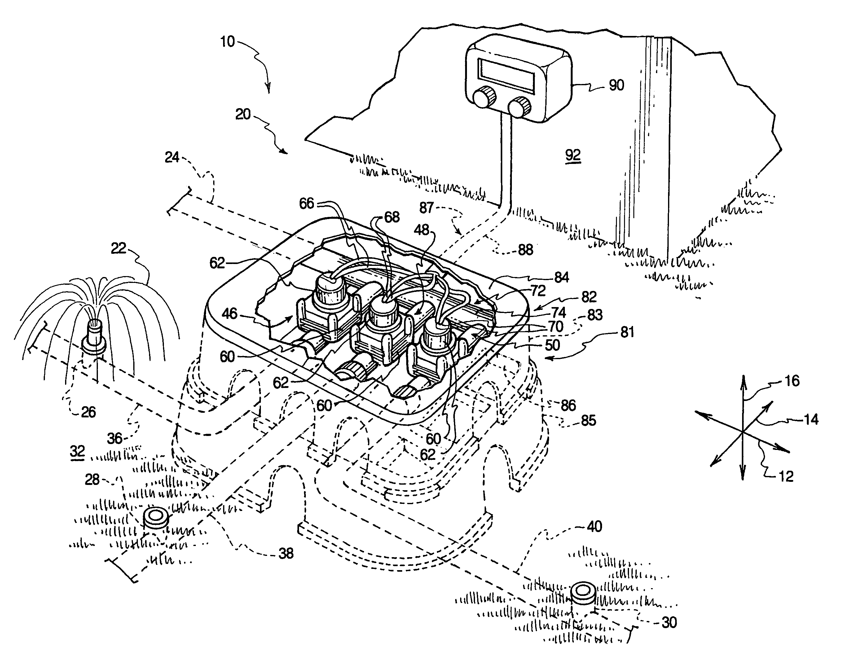
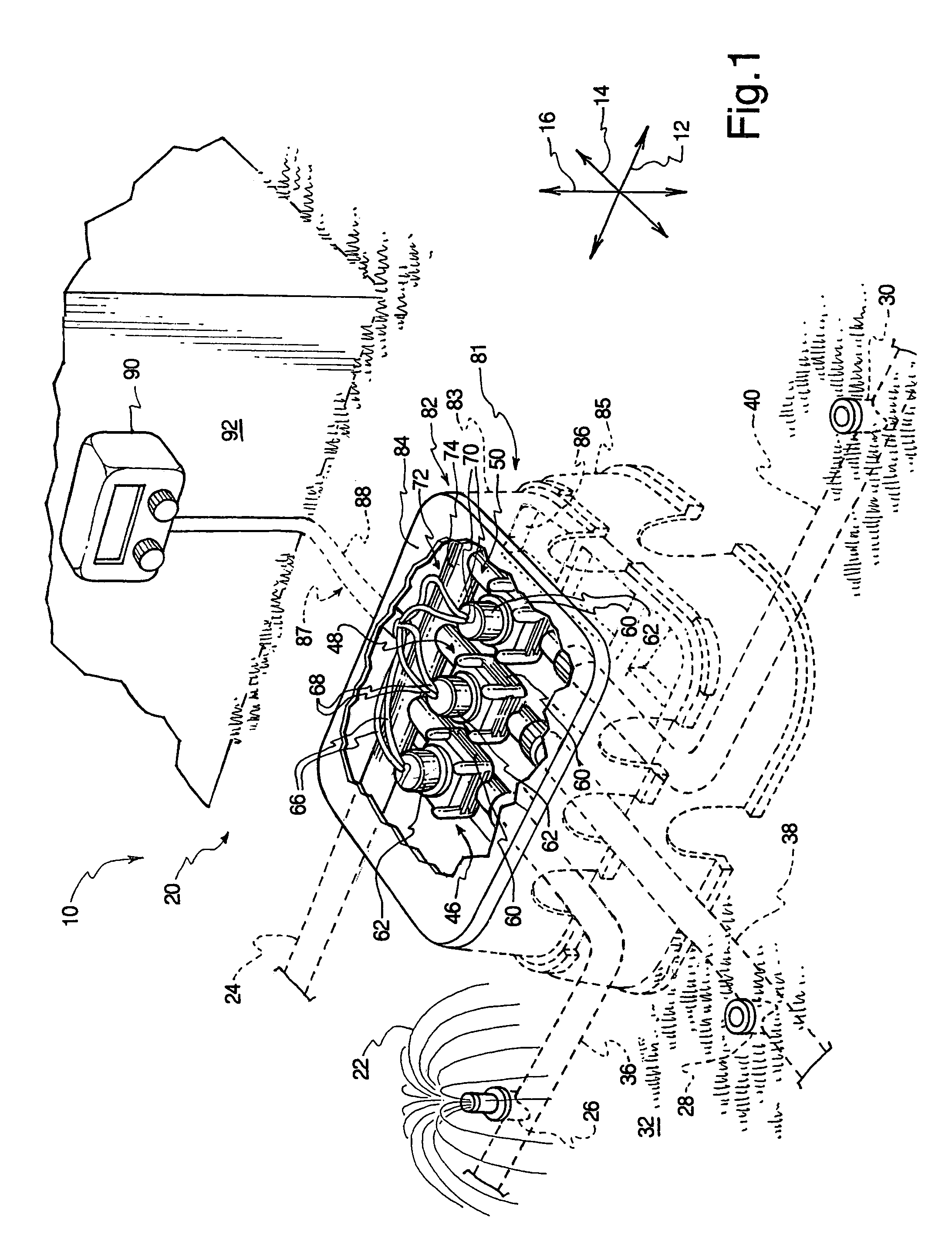
[0014]Each valve assembly also has a pair of wires that conveys a valve activation signal to the actuator to move the valve assembly between the open and closed configurations. The valve assemblies may be connected to a feeder conduit to form a manifold that receives water from a main line. The manifold may be disposed underground, within a valve containment assembly. The valve containment assembly may be uniquely designed to provide the valve assembly with some protection from water or soil infiltration.
[0039]The valve containment assemblies and related methods of the invention provide a greater degree of protection against water and soil contamination of valving system components. Furthermore, the valve containment assemblies are relatively simple, inexpensive, and easy to install. These and other features and advantages of the present invention will become more fully apparent from the following description and appended claims, or may be learned by the practice of the invention as set forth hereinafter.

Problems solved by technology

Unfortunately, known valve box designs often do not sufficiently protect the valves.
The hole in which the valve box is located may fill with water due to leakage from the irrigation system components or from precipitation.
Hence, many known valve box designs permit valve components to be relatively easily damaged due to water infiltration.
Furthermore, water leakage or simple settling over time may cause the earth in the sides of the hole to begin filling the hole by moving into the valve area.
Thus, the valves may be buried and potentially damaged or made inaccessible by the accumulated soil.
This may also impair operation of the valves or make them inconvenient to access for maintenance or replacement.
Yet further, many known valve boxes are relatively inflexible in design.
These burdensome tasks add significantly to the time required to install the irrigation system.

Method used


Image

  • Enhanced irrigation valve platform assembly
  • Enhanced irrigation valve platform assembly
  • Enhanced irrigation valve platform assembly

Examples


Embodiment Construction

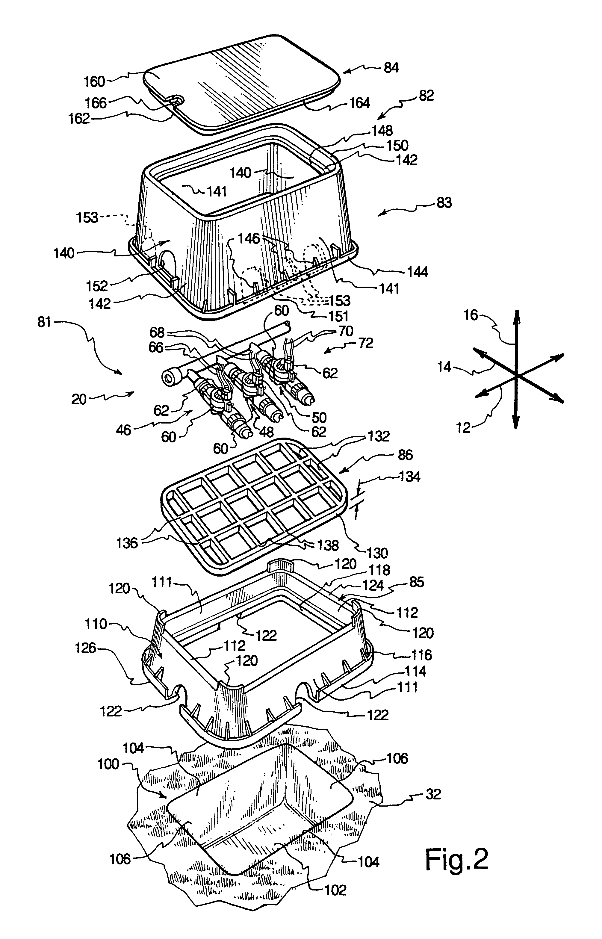
[0050]The presently preferred embodiments of the present invention will be best understood by reference to the drawings, wherein like parts are designated by like numerals throughout. It will be readily understood that the components of the present invention, as generally described and illustrated in the figures herein, could be arranged and designed in a wide variety of different configurations. Thus, the following more detailed description of the embodiments of the apparatus, system, and method of the present invention, as represented in FIGS. 1 through 9, is not intended to limit the scope of the invention, as claimed, but is merely representative of presently preferred embodiments of the invention.

[0051]For this application, the phrases “connected to,”“coupled to,” and “in communication with” refer to any form of interaction between two or more entities, including mechanical, electrical, magnetic, electromagnetic, and thermal interaction. The phrase “attached to” refers to a for...


PUM


Abstract

A valve containment assembly for an irrigation system may have a first side wall unit, a grate, a second side wall unit, and a lid. The first side wall unit may be disposed on the floor of a hole. The grate may be positioned in the first side wall unit to support a manifold. The second side wall unit rests on the first side wall unit to cover the manifold and the lid may be disposed on top of the side wall unit. The first side wall unit and the grate elevate the manifold above the floor of the hole to reduce interference of soil and water with the manifold. Additional side wall units may be used to provide additional height. Any of the side wall units may have frangible portions that break away to permit passage of conduits into the valve containment assembly.

Description

RELATED APPLICATIONS[0001]The present application claims the benefit of U.S. Provisional Application No. 60 / 439,671, filed Jan. 13, 2003 and entitled ENHANCED IRRIGATION VALVE CONTAINMENT ASSEMBLY, which is incorporated herein by reference.BACKGROUND OF THE INVENTION[0002]1. Field of the Invention[0003]The present invention relates to irrigation systems and methods. More specifically, the present invention relates to an apparatus and method for containing one or more underground irrigation valves.[0004]2. Description of Related Art[0005]Irrigation not only permits foodstuffs to be grown, but also enables the cultivation of attractive plant life that otherwise would not have sufficient water to thrive. Many households now utilize irrigation systems, or “sprinkler systems,” to provide irrigation in a comparatively uniform and trouble-free manner.[0006]Often, a control unit such as a timer is used to regularly initiate operation of the sprinkler system to automatically provide the desi...

Claims


Application Information

Patent Timeline
Patent Type & Authority Patents(United States)
IPC IPC(8): E02B11/00
CPCA01G25/162Y10T137/7021Y10T137/7025Y10T137/6995
Inventor ERICKSEN, KENT C.DAY, KEVINOLSEN, CHRISTIAN M.SCHAPPER, AARONENCE, ALAN T.
Owner HUSQVARNA AB
Why Eureka
Try Eureka