Cover member for illuminated pushbutton switch

a pushbutton switch and cover technology, applied in the field of pushbutton switches, can solve the problems of increasing the number of process steps, the difficulty of adjusting the size of the cover member, and the low intensity of the illumination light, and achieve the effect of low cost, high luminance illumination, and low cos

Inactive Publication Date: 2006-02-28
POLYMATECH CO LTD
View PDF36 Cites 24 Cited by
  • Summary
  • Abstract
  • Description
  • Claims
  • Application Information

AI Technical Summary

Benefits of technology

[0012]An illuminated pushbutton switch cover member in accordance with the present invention has been made under these circumstances. That is, an object of the present invention is to provide an illuminated pushbutton switch cover member which is capable of illumination at a higher luminance and which can be produced at a low cost.

Problems solved by technology

The above-described conventional illuminated pushbutton switch cover member 1 has a certain effect of illumination of the triangular symbols 5a formed in the indicator portions 5b, but has a problem in that the intensity of light for illumination is low.
The method of coloring the key sheet 3, however, requires a secondary vulcanization process after kneading and forming silicone rubber, i.e., the material of the key sheet 3, and therefore entails the drawback of increasing the manufacturing cost.
This method also entails a problem in that a low-molecular-weight siloxane component remaining in silicone rubber is scattered to cause a continuity fault or the like in the switch.
On the other hand, the method of additionally forming a light-blocking layer has the drawback of increasing the number of process steps and is disadvantageous in terms of manufacturing time and cost.

Method used


Image

  • Cover member for illuminated pushbutton switch
  • Cover member for illuminated pushbutton switch
  • Cover member for illuminated pushbutton switch

Examples


first embodiment

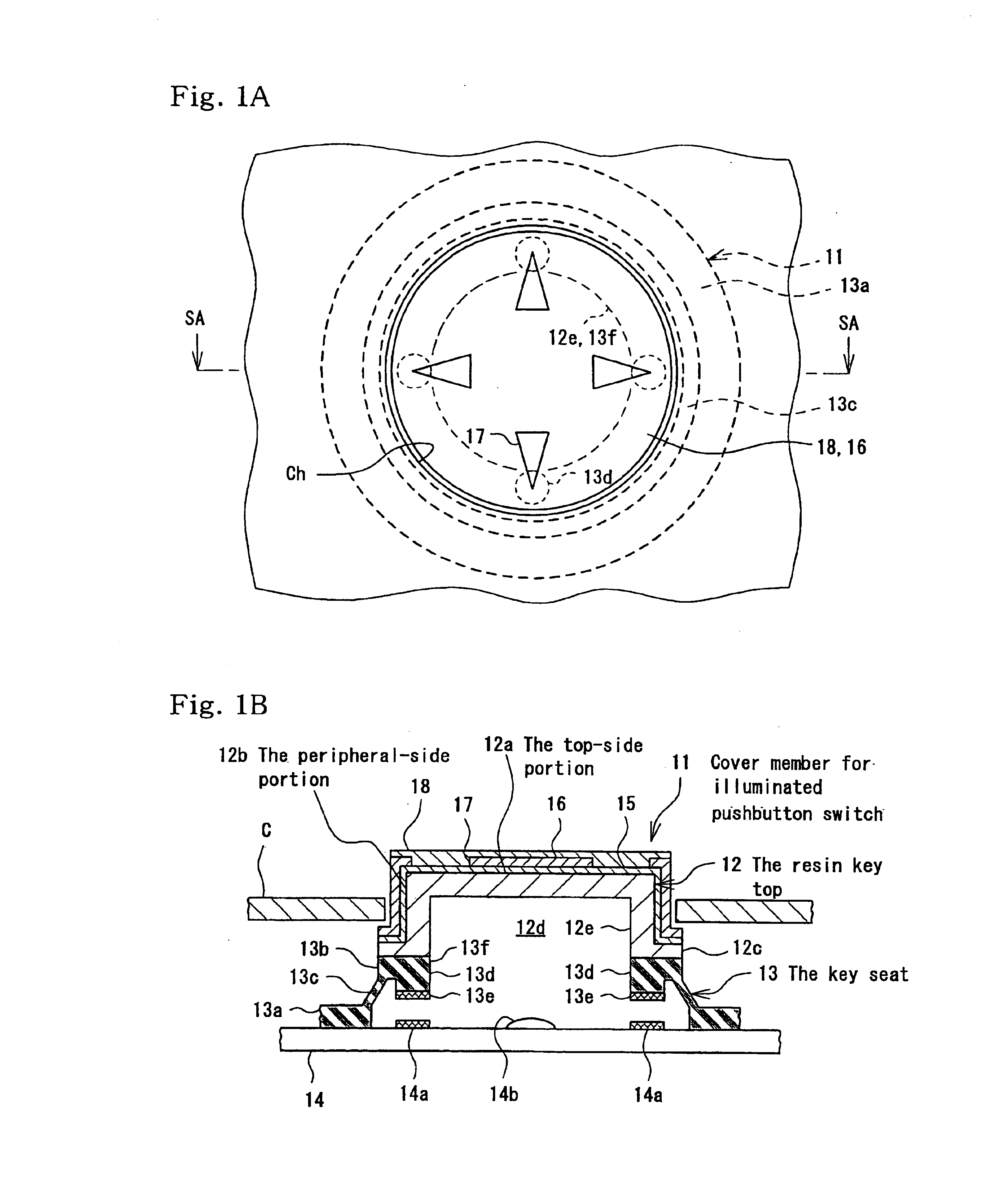
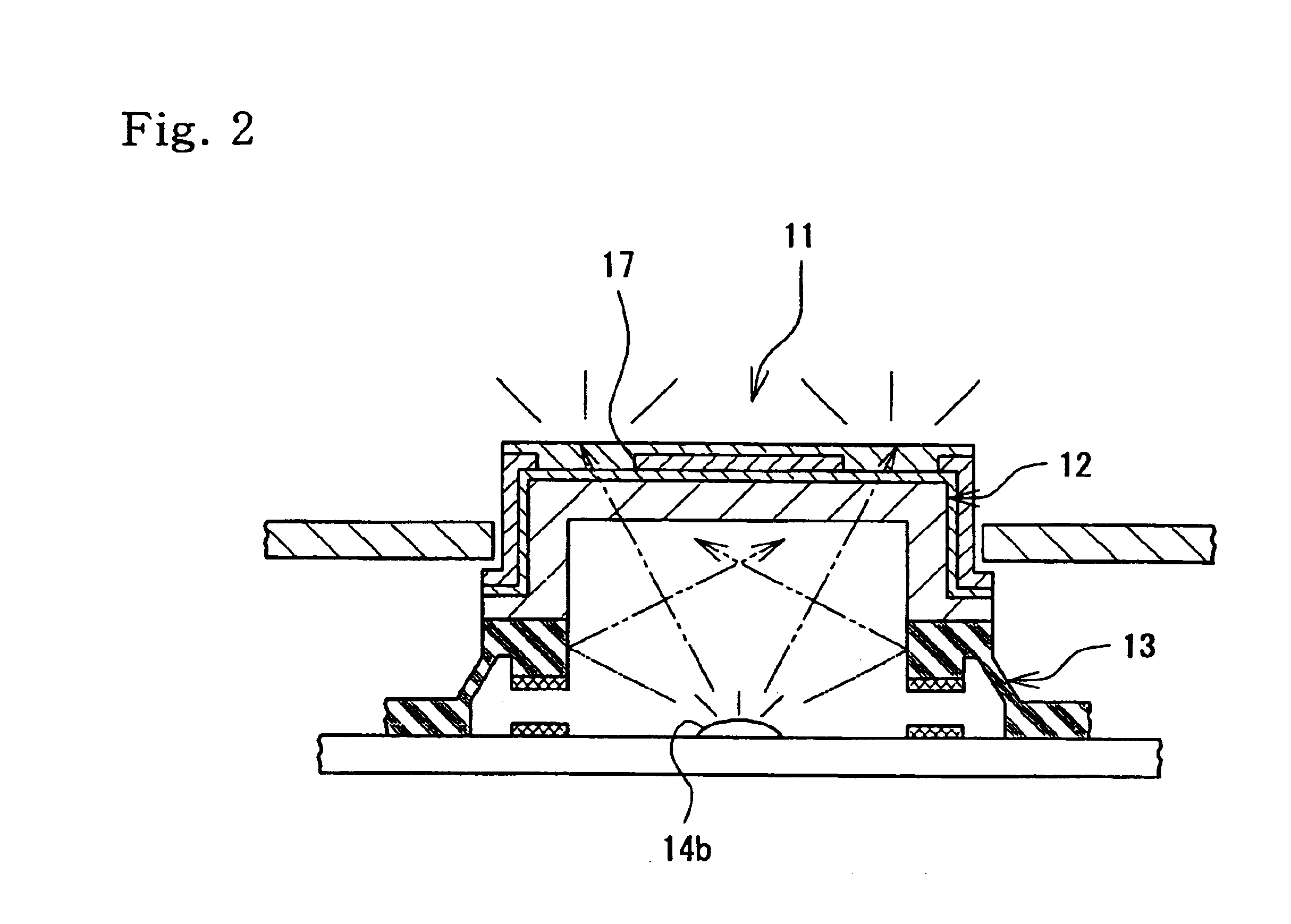
[0038]A first embodiment will be described with reference to FIGS. 1A, 1B, and 2 of the drawings. A cover member 11 for an illuminated pushbutton switch according to this embodiment has, as shown in FIG. 1B, a resin key top 12 made of a transparent resin, and a light-blocking key sheet 13 made of a rubber-like elastic material. The resin key top 12 and the light-blocking key sheet 13, combined integrally with each other, and a circuit board 14 on which other switch devices (not shown) are mounted, constitute a pushbutton switch.

[0039]The resin key top 12 has a flat disk-like top-side portion 12a, a cylindrical peripheral-side portion 12b extending downward from the peripheral end of the top-side portion 12a, and an annular flange portion 12c extending outwardly from a lower end portion of the peripheral-side portion 12b. The entire resin key top 12 is generally in a hat-like form with a cavity 12d formed thereon. The resin key top 12 is formed by injection molding of a transparent h...

second embodiment

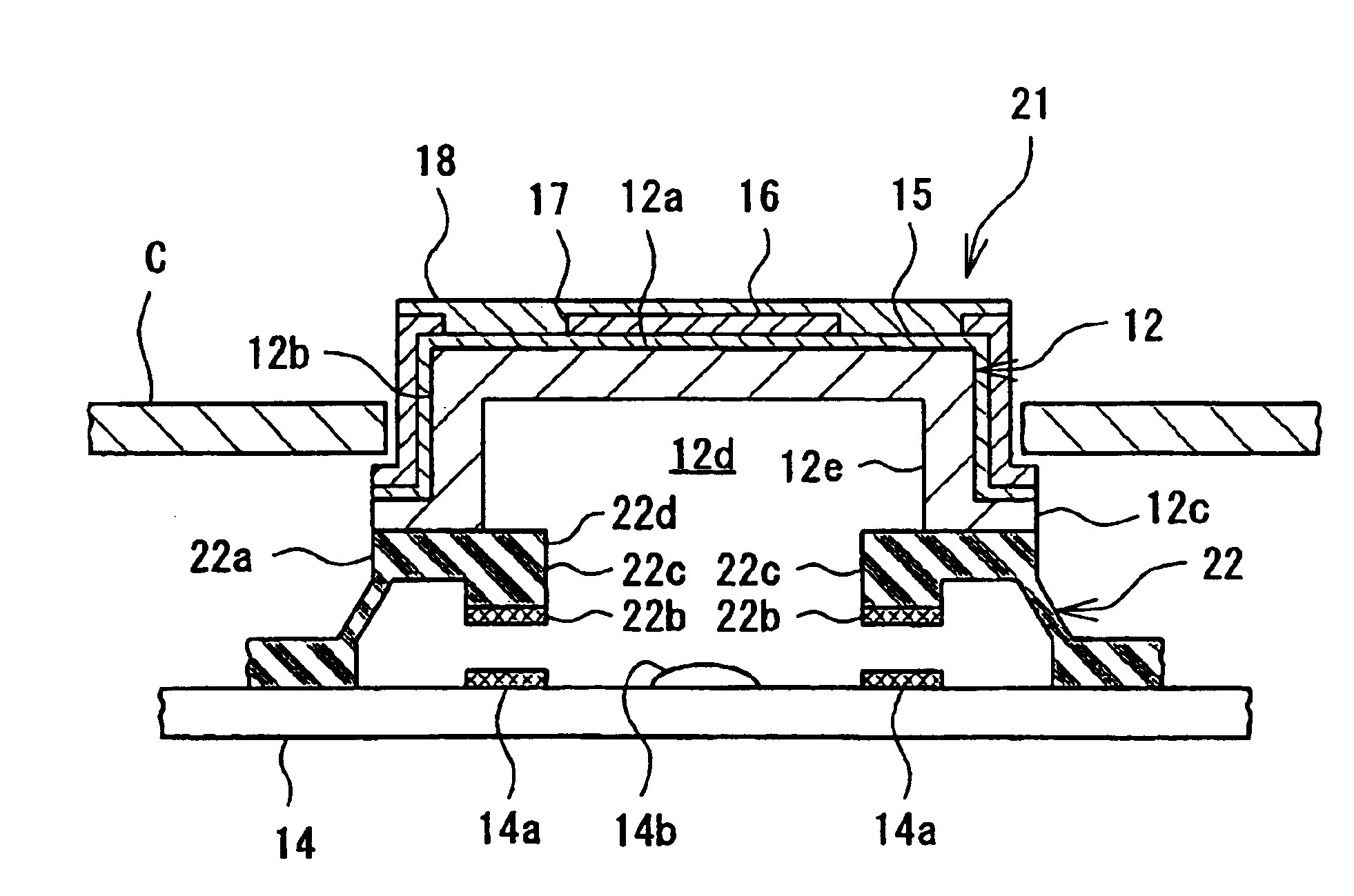
[0054]A second embodiment of the present invention will now be described with reference to FIGS. 3A, 3B, and 4 of the drawings. In the second embodiment, the pushbutton switch cover member 11 of the first embodiment is modified to obtain a pushbutton switch cover member 21, as shown in FIGS. 3A, 3B, and 4. The pushbutton switch cover member 21 of this second embodiment differs from the cover member 11 of the first embodiment only in the structure of a key sheet 22, and is the same as the cover member 11 in other respects.

[0055]Four pressing projections 22c having contacts 22b attached to their ends are also formed on a key top supporting portion 22a of the key sheet 22. In the structure of this key sheet 22, however, each pressing projection 22cprojects inwardly in an opening 22d for passage of light. In this projection structure, light to be projected to the peripheral-side portion 12b of the resin key top 12 is partly blocked by the pressing projections 22c. The indicator portions...

third embodiment

[0057]A third embodiment of the present invention will now be described with reference to FIG. 5 of the drawings. In the third embodiment, a pushbutton switch cover member 31 has a transparent resin key top 32 and a key sheet 33 formed as shown in FIG. 5. The thickness of the key top supporting portion 33a of the key sheet 33 in this embodiment is larger than that in the first embodiment. The structure of the key sheet 33 is the same as that in the first embodiment in other respects.

[0058]The resin key top 32 has a top-side portion 32a and a peripheral-side portion 32b but has no flange portion corresponding to the flange portion 12c in the hat-like sectional configuration in the above-described embodiments. The thickness of the key top supporting portion 33a is increased as described above by the amount corresponding to the thickness of the flange portion removed. Also, leakage of light through the flange portion is prevented by removing the flange portion, thus achieving a complet...


PUM


Abstract

An illuminated pushbutton switch cover member has a key seat and a resin key top. An indicator portion provided in the resin key top is illuminated with light from an internal light source provided below the key seat, and the light is emitted from the inside to the outside of the cover member through the indicator portion. The cover member is constructed by joining the resin key top to the key seat. The key seat is formed of a thermoplastic elastomer that prevents leakage of light, and an opening for passage of light is formed in the key seat to expose the bottom side of the resin key top to the internal light source. Thus, light from the internal light source can reach the bottom side of the resin key top directly without being attenuated. The indicator portion of the resin key top can therefore be illuminated with high luminance.

Description

BACKGROUND OF THE INVENTION[0001]1. Field of the Invention[0002]The present invention relates generally to pushbutton switches, and in, particular, to a cover member for an illuminated pushbutton switch having an illumination function for emitting light from the inside to the outside for use with pushbutton switches requiring input operations in a dark place, such as various switches for telephones, AV apparatuses, remote controllers, vehicle interior equipment, and so forth.[0003]2. Description of the Related Art[0004]Illuminated-type pushbutton switches are frequently used for switches requiring input operations in dark places, such as various switches for electronic equipment such as portable telephones and AV apparatuses, and vehicle interior equipment mounted on the vehicle, and so forth. Such illuminated-type switches have a key top with an indicator portion in which a letter, a numeric character, a symbol, a pattern or the like is formed, and through which light from an inter...

Claims


Application Information

Patent Timeline
Patent Type & Authority Patents(United States)
IPC IPC(8): H01H9/00H01H25/00H01H9/18H01H25/04
CPCH01H25/041H01H9/182H01H2009/183H01H2233/07H01H2221/002H01H2221/07H01H2229/046H01H2009/187
Inventor MAEDA, JUNYANISHIMURA, TAKESHI
Owner POLYMATECH CO LTD
Why Eureka
Try Eureka