
Rechargeable battery pack with adaptive regenerative energy control and method thereof

a rechargeable battery and energy control technology, applied in battery/fuel cell control arrangement, secondary cell servicing/maintenance, transportation and packaging, etc., can solve the problem of serious damage to the battery, inflexible fixed headroom approach, and inability to meet the charging regimen where the battery is charged to 100%

Inactive Publication Date: 2006-02-28
ENERDEL
View PDF20 Cites 36 Cited by
  • Summary
  • Abstract
  • Description
  • Claims
  • Application Information

AI Technical Summary

Benefits of technology

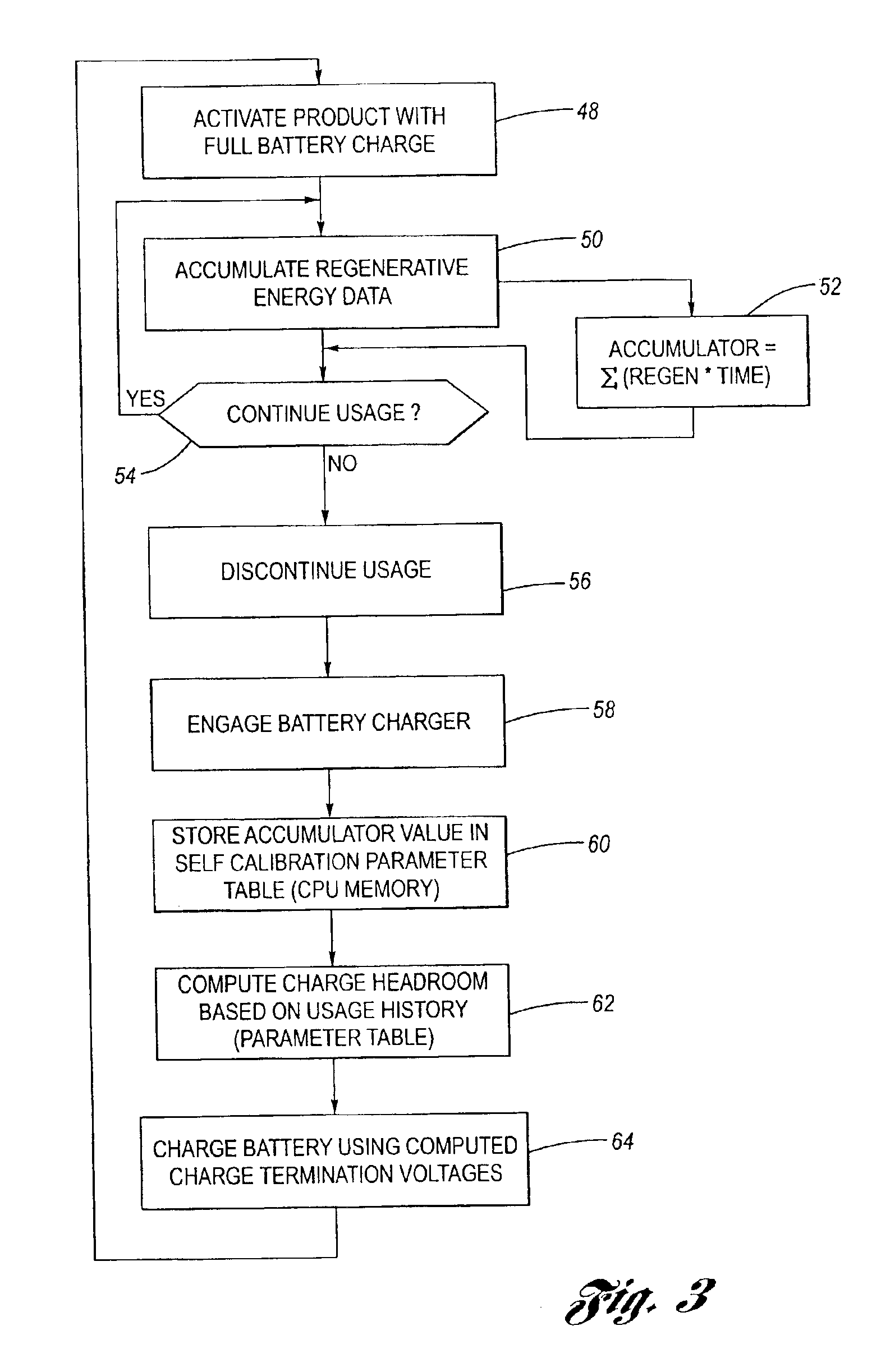
"The present invention provides a method and system for dynamically adapting a charging strategy for a rechargeable battery based on its actual use, to maximize the duration of use of an application that is using the battery while minimizing the occurrence of overcharging. This allows greater applicability of battery technologies that are more intolerant to overcharging, and eliminates the need for extra circuitry or structure previously necessary to dissipate heat due to overcharging. The method involves determining an operating characteristic of an application employing the battery pack, adjusting a charging strategy based on the observed operating characteristic, and charging the battery pack in accordance with the determined regenerative energy parameter."

Problems solved by technology

However, where the usage and regeneration patterns are expected to be (and are) unpredictable and variable, the fixed headroom approach is inflexible and inefficient.
That is, in many instances, the additional voltage, and in part, heat due to overcharging may seriously impair or damage the battery.
Accordingly, the known charging regimen where the battery is charged to 100% is realistically unavailable in the circumstances described above, since the possibility of receiving regenerative energy when the battery is fully charged could have catastrophic results.

Method used


Image

  • Rechargeable battery pack with adaptive regenerative energy control and method thereof
  • Rechargeable battery pack with adaptive regenerative energy control and method thereof

Examples


Embodiment Construction

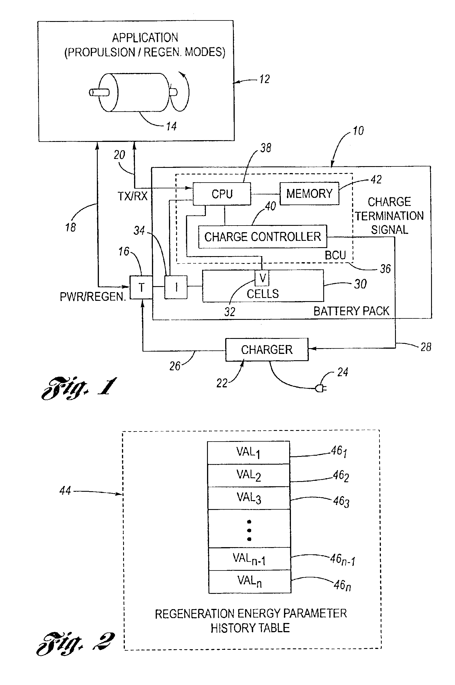
[0018]Referring now to the drawings wherein like reference numerals are used to identify identical components in the various views, FIG. 1 is a simplified, schematic and block diagram view of an inventive battery pack 10 according to the invention suitable for use in connection with any one or more of a plurality of exemplary applications 12. Application 12, in the illustrated embodiment, is of the type employing a dynamoelectric machine 14, which may alternatively be configured for operation (i) in a first mode wherein the machine 14 is used for propulsion torque, or (ii) in a second mode different from the first mode wherein the machine 14 is configured for the production of regenerative energy (i.e., it is configured as a generator). For example, such applications may include, but are not limited to, self-propelled vehicle applications, although other application stationary in nature (i.e., rotating systems having loads with inertia) are also included within the spirit and scope ...


PUM

PropertyMeasurementUnit
charge termination voltageaaaaaaaaaa
regenerative energyaaaaaaaaaa

Abstract

A charging strategy for a rechargeable battery pack is disclosed. The battery pack is used in an application that includes a dynamoelectric machine that may operate as a motor, drawing power from the battery pack, or as a generator, delivering regenerative energy to the battery pack. The strategy monitors the nature, intensity, duration and frequency, among other things, associated with encountered episodes of regenerative energy from the dynamoelectric machine, and adjusts subsequent recharging processes to allow a calculated amount of headroom to accommodate regenerative energy inputs in the future, which may be assumed to be equal in nature, intensity, duration and frequency to what has already been observed. Overcharging is reduced or eliminated, while maximizing the amount of charge on the battery pack, and thus duration of use.

Description

CROSS-REFERENCE TO RELATED APPLICATIONS[0001]This application claims the benefit of U.S. Provisional Application Ser. No. 60 / 389,423 filed Jun. 17, 2002, the disclosure of which is hereby incorporated by reference in its entirety.BACKGROUND OF THE INVENTION[0002]1. Technical Field[0003]The invention relates generally to energy-based systems, and in particular to a method and system for adaptive regenerative energy control.[0004]2. Discussion of the Background Art[0005]It is known in many applications, including self-propelled vehicle applications, to employ a dynamoelectric machine in a first mode as a motor in order to provide propulsion torque. In such applications, it is also known to reconfigure the dynamoelectric machine in a second mode as a generator, in order to capture and convert some of the potential or kinetic energy associated with the application into output electrical power, a process known as regeneration (“regenerative energy”). Moreover, in such applications, it is...

Claims


Application Information

Patent Timeline
Patent Type & Authority Patents(United States)
IPC IPC(8): H01M10/44B60L11/18H02J7/14
CPCB60L11/1851H02J7/1446Y02T10/92Y02T10/705Y02T10/7005B60L58/10Y02T10/70
Inventor MOORE, STEPHEN W.HUSTED, HARRY L.
Owner ENERDEL
Learn More