Radio communication scheme

Inactive Publication Date: 2006-02-28
KK TOSHIBA
View PDF8 Cites 117 Cited by
  • Summary
  • Abstract
  • Description
  • Claims
  • Application Information

AI Technical Summary

Benefits of technology

[0010]The present invention is proposed in view of the above mentioned circumstances. It is therefore an object of the present invention to provide a radio base station controller and a radio mobile station which c

Problems solved by technology

However, if a radius of a cell covered by each base station 202 is small, a switching opportunity of a communication line is frequently done, which requires a very complex process.
If the conventional hand-over technique is applied to such AHS, a rate of the hand-over process occupying the communication process becomes very large.
This results in a problem that a communication efficiency becomes very poor.
So, a failure of th

Method used


Image

  • Radio communication scheme
  • Radio communication scheme
  • Radio communication scheme

Examples


Example

[0046](First Embodiment)

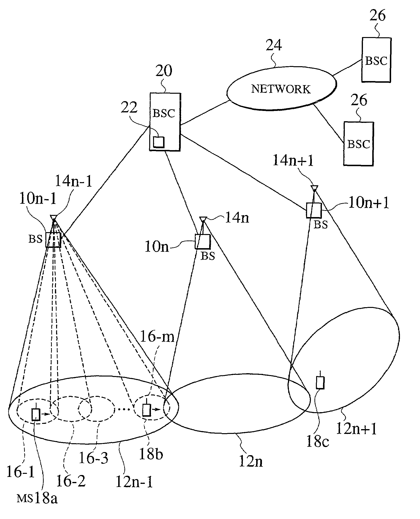
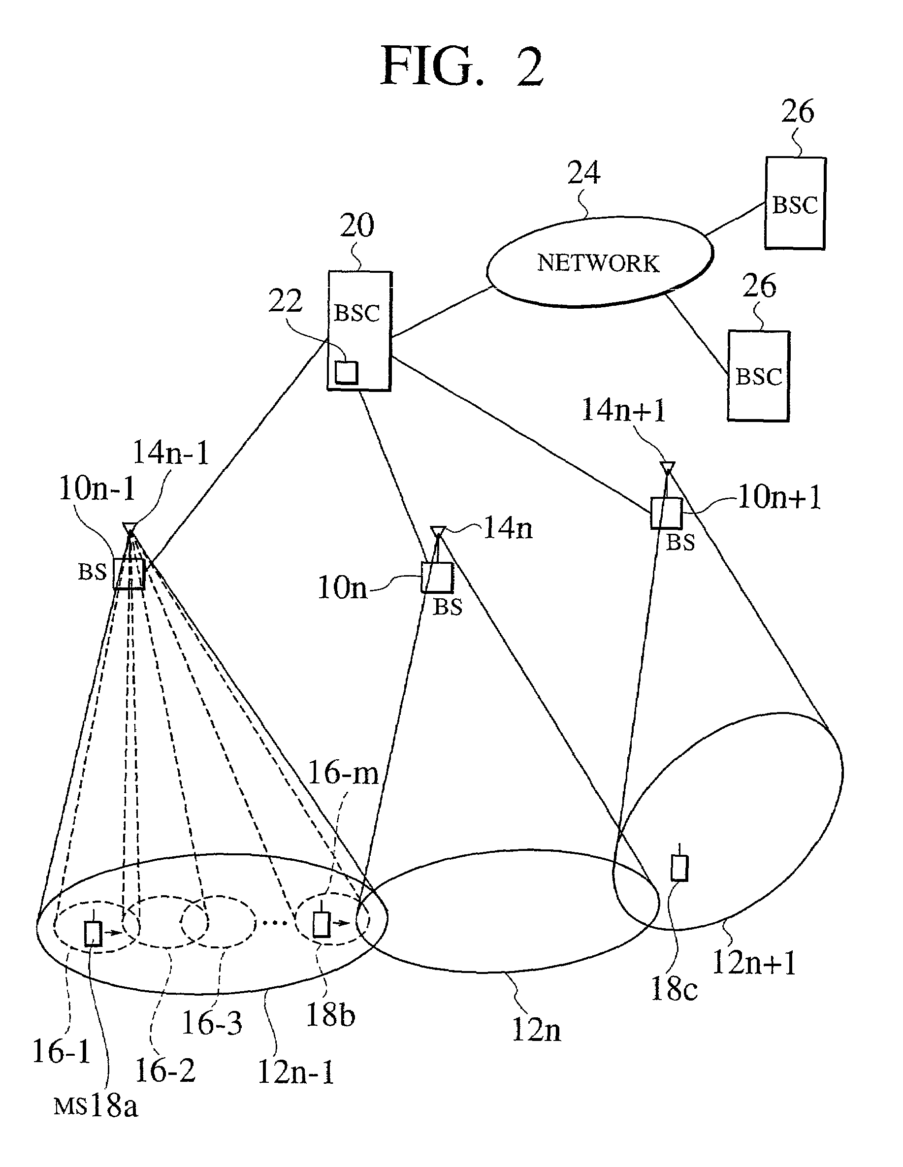
[0047]FIG. 2 is a view showing a configuration of a radio communication system according to a first embodiment of the present invention. In the radio communication system according to the first embodiment of the present invention, a plurality of areas (cells) covered by each base station constitute an entire service area of a mobile communication network. In FIG. 2, the explanation is done under the assumption that the number of base stations managed by one base station controller is 3, for the purpose of simple explanation.

[0048]In the radio communication system according to the first embodiment of the present invention in FIG. 2, areas (hereafter, referred to as base station areas) 12n−1, 12n and 12n+1 managed by radio base stations 10n−1, 10n and 10n+1 divide parts of an service area and covers them. The respective radio base stations 10n−1, 10n and 10n+1 have antennas 14n−1, 14n and 14n+1, respectively, which can generate a plurality of beam patterns. Eac...

Example

[0091](Second Embodiment)

[0092]A second embodiment of the present invention will be described below. In this second embodiment, a setting example of a radio channel in the first embodiment of the present invention is explained by using five examples.

[0093](First Radio Channel Setting Example)

[0094]FIG. 9 is a view explaining a first radio channel setting example according to the second embodiment of the present invention. In FIG. 9, the explanation is done under the assumption that the number of radio base stations managed by one radio base station controller is 5, for the purpose of simple explanation. Also, it is assumed that the number of radio channels which can be used within one base station controller is 3.

[0095]In a radio communication system shown in FIG. 9, a radio base station controller 86 manages five radio base stations 88 (88a, 88b, 88c, 88d and 88e) and carries out the respective controls. Those five radio base stations 88 are installed for each approximately “r” int...

Example

[0134]A third embodiment of the present invention will be described below. The first and second embodiments are the embodiment with regard to the hand-over process between the radio base stations within the area managed by one radio base station controller. However, this third embodiment is an embodiment with regard to a hand-over process between two different radio base station controllers. FIG. 15 is a view showing a configuration of a radio communication system according to the third embodiment of the present invention. In the radio communication system according to the third embodiment of the present invention, similarly to the first embodiment, a plurality of areas (cells) managed by each base station are gathered to constitute the entire service area in the mobile communication network. Also, in FIG. 15, the explanation is done under the assumption that the number of base stations managed by one base station controller is 3, for the purpose of simple illustration.

[0135]In the ...


PUM


Abstract

A radio communication system having a radio base station controller which is connected to a plurality of base stations, and assigns a fixed channel to each of the radio mobile stations. The radio base station controller also controls the beam patterns of the radio base stations to communicate with the radio mobile stations. The radio base station controller, when transmitting to and receiving from the different radio mobile stations to which the same channel is assigned, controls the beam patterns so that the channels do not interfere with each other.

Description

CROSS REFERENCE TO THE RELATED APPLICATION[0001]The subject application is related to subject matter disclosed in the Japanese Patent Application No. Heill-356632 filed in Dec. 15, 1999 in Japan, to which the subject application claims priority under the Paris Convention and which is incorporated by reference herein.BACKGROUND OF THE INVENTION[0002]1. Field of the Invention[0003]The present invention relates to a radio communication system, a radio communication method, a radio base station controller and a radio mobile station which are used in a mobile communication service and the like. More particularly, the present invention relates to a technique for keeping a communication even if a radio mobile station is moved in a radio communication system, namely, a hand-over technique.[0004]2. Description of the Related Art[0005]FIG. 1 shows an example of a radio communication system in which a plurality of base stations are connected to a mobile services switching center. As shown in F...

Claims


Application Information

Patent Timeline
IPC IPC(8): H04Q7/00H01Q1/24H01Q3/26H04B7/26H04W16/32H04W88/08
CPCH01Q1/246H01Q3/2676H04W16/32H04W88/085
Inventor TOSHIMITSU, KIYOSHITSUJIMURA, AKIHIROITO, KUNIAKIOBAYASHI, SHUICHISHOKI, HIROKI
Owner KK TOSHIBA
Why Eureka
Try Eureka