
Test chart color measuring system and a color output apparatus correcting system

a color measuring system and color output technology, applied in the direction of optical radiation measurement, image enhancement, instruments, etc., can solve the problems of poor operability, long time-consuming, and expensive manufacture of test charts

Inactive Publication Date: 2006-02-28
MINOLTA CO LTD
View PDF10 Cites 31 Cited by
  • Summary
  • Abstract
  • Description
  • Claims
  • Application Information

AI Technical Summary

Benefits of technology

"The present invention provides a test chart color measuring system and a color output apparatus correcting system that are free from the problems of prior art. The system includes a color image taking apparatus for taking up a color image of a test chart and an image processor for extracting image signals corresponding to color samples and calculating a color value of each color sample using the extracted image signal. The system also includes a test chart output controller for controlling a color output apparatus to output a test chart for correction and a correction data calculator for calculating correction data for the color output apparatus based on the color values of the color samples. The technical effects of the invention include improved accuracy in color measurement and correction, improved efficiency in color output, and improved user experience."

Problems solved by technology

It takes a long time if the colors of the test chart are measured for each color sample using a usual manually operable colorimeter.
This results in a poor operability.
However, such a test chart is expensive to manufacture and is disadvantageous in terms of costs.
Further, since either colorimeter is of the scan type, the more the color samples, the longer time is required for the color measurement.
Such considerations lead to increased costs.

Method used


Image

  • Test chart color measuring system and a color output apparatus correcting system
  • Test chart color measuring system and a color output apparatus correcting system
  • Test chart color measuring system and a color output apparatus correcting system

Examples


Embodiment Construction

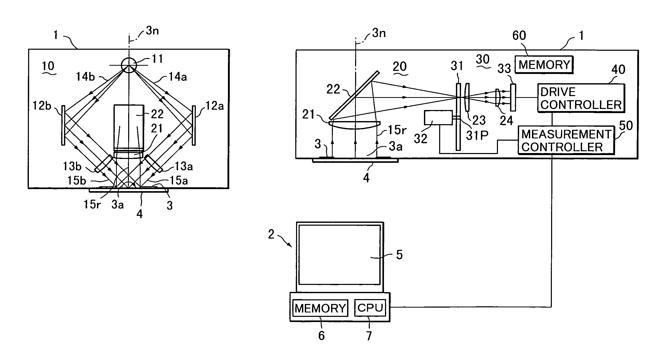
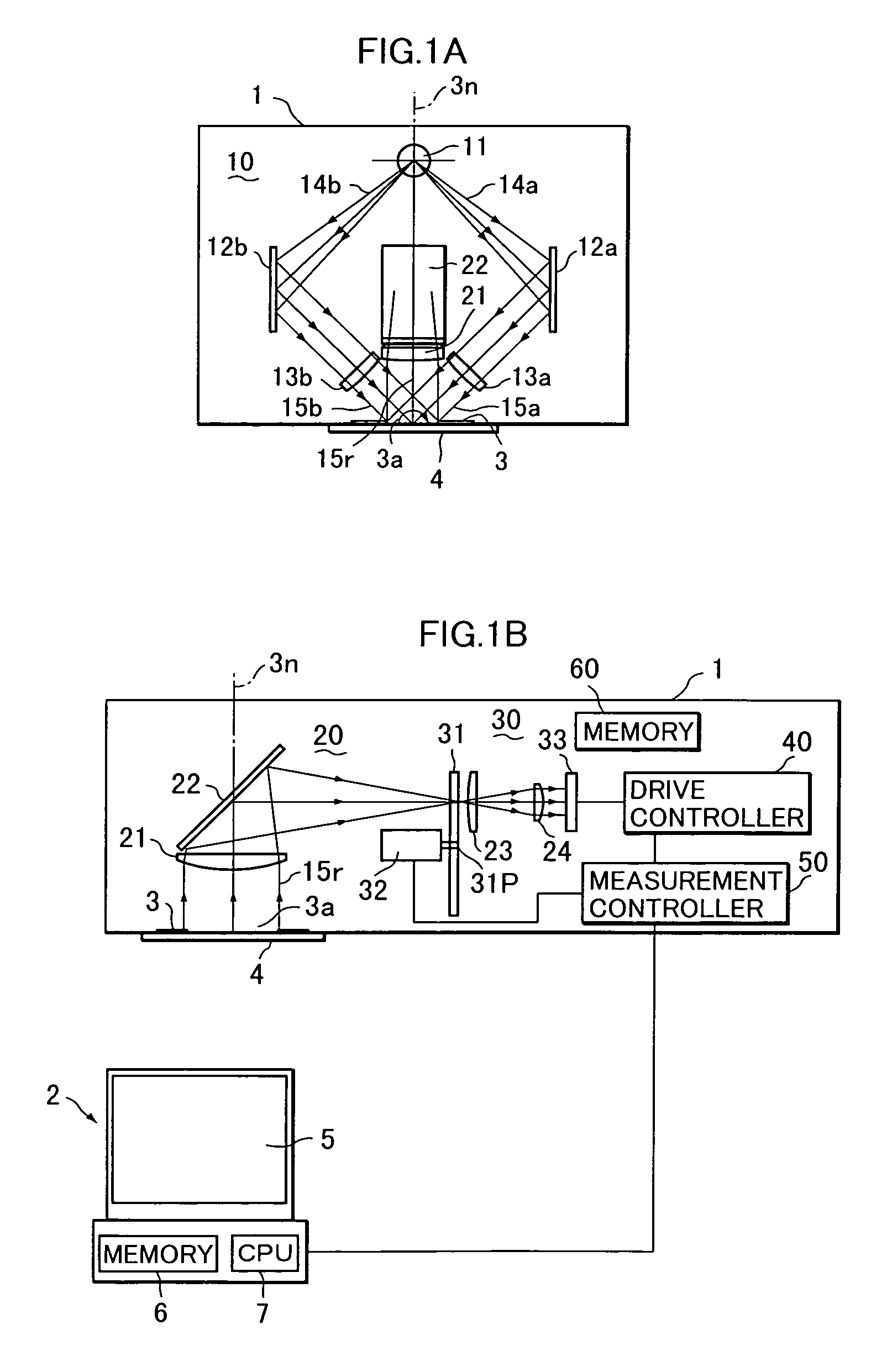
[0030]Referring to FIGS. 1A and 1B, a test chart color measuring system 1 according to an embodiment of the invention is comprised of a color measuring head 1 and a personal computer (PC) 2. The color measuring head (color image taking apparatus) 1 includes an illuminating unit 10, a light receiving optical system 20, a color image pickup unit 30, a drive controller 40 and a measurement controller 50, which are integrally accommodated in a head main body. At the bottom end of the main body of the color measuring head 1 is arranged a specimen mask 3, which is formed with a substantially rectangular sample opening 3a. The color measuring head 1 picks up a color image of a test chart 4 as a measurement specimen with the test chart 4 placed to face the specimen opening 3a.

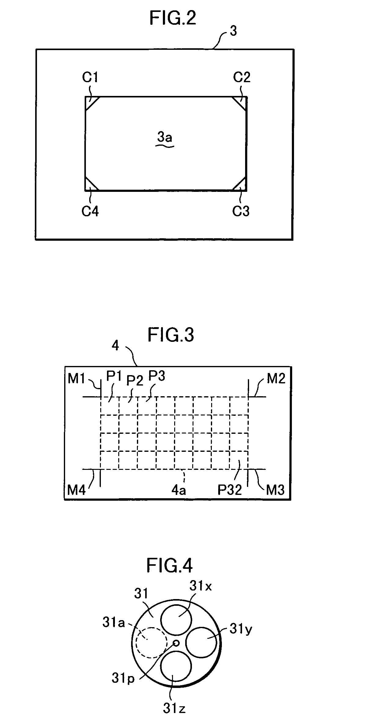
[0031]The test chart 4 is such that specified color samples P1 to P32 are arrayed in sections (indicated by broken lines in FIG. 3) obtained by dividing a rectangular sample area 4a like a matrix as shown in FIG. 3. E...


PUM


Abstract

A color measuring head is provided with an illuminating unit, a light receiving optical system, a color image pickup unit, a drive controller and a measurement controller, and picks up an image of a test chart as a measurement specimen placed to face a specimen opening. A personal computer is provided with a monitor, a memory unit, and a CPU. The CPU calculates color values of color samples by reading and implementing a control program stored in the memory unit. The color of the test chart in which a plurality of color samples are arrayed can be automatically measured within a short period of time.

Description

[0001]This application is based on patent application No. 11-278545 filed in Japan, the contents of which are hereby incorporated by references.BACKGROUND OF THE INVENTION[0002]This invention relates to techniques concerning measurement of a test chart used to correct output colors of a color output apparatus such as color printer or color copier and correction of the output colors using a color measurement result.[0003]Generally, output colors of a color output apparatus such color printer or color copier slightly vary due to environmental factors such as temperature and humidity and with the lapse of time even within one day. Particularly, the output colors are corrected once or more within one day in a color output apparatus used as a small-sized printing apparatus. A test chart in which a plurality of color samples having different tones and different densities are arrayed is used for the correction of the output colors. Specified control information is sent from, for example, a...

Claims


Application Information

Patent Timeline
Patent Type & Authority Patents(United States)
IPC IPC(8): G06K9/00B41J2/525G01J3/10G01J3/28G01J3/51G01J3/52G06T1/00G06T5/00H04N1/00H04N1/46H04N1/60
CPCG01J3/10H04N1/6033G01J3/51G01J3/52G01J3/524H04N1/60G01J3/2823G01J3/0208G01J3/021G01J3/0216
Inventor IMURA, KENJI
Owner MINOLTA CO LTD
Learn More