System and method deghosting mosaics using multiperspective plane sweep

a multi-perspective plane sweep and mosaic technology, applied in image enhancement, instruments, editing/combining figures or texts, etc., can solve problems such as local misregistration between the combined images, ghosting due to the presence of parallax, and large computational costs of large sets of overlapping images for generating mosaics

Inactive Publication Date: 2006-02-28
MICROSOFT TECH LICENSING LLC
View PDF7 Cites 66 Cited by
  • Summary
  • Abstract
  • Description
  • Claims
  • Application Information

AI Technical Summary

Benefits of technology

[0029]FIG. 4B provides exemplary photographic images showing the effect of the perspective warping of the images of FIG. 3B to place the images into a common image plane.

Problems solved by technology

Unfortunately, using large sets of overlapping images having a high degree of overlap for generating mosaics is typically computationally expensive.
Further, where the set of overlapping images available for generating a mosaic comprises a sparse or limited set of images taken at slightly displaced locations, the problem of ghosting due to the presence of parallax becomes a major concern.
Specifically, any deviations from a pure parallax-free motion model or an ideal pinhole camera model can result in local misregistrations between the combined images.
Unfortunately, while useful, because the aforementioned patch-based deghosting technique is purely image-based, it is only capable of addressing small amounts of motion parallax.
Consequently, this scheme can not fully address significant parallax problems.
Further, the corrective warping used in this patch-based deghosting technique often produces unrealistic-looking results.
In addition, the patch-based deghosting technique summarized above tends to be computationally expensive.
Unfortunately, this scheme can not provide a satisfactory solution in the case of sparse sampling, such as where overlap between images is 50% or less and where parallax is a significant concern.
In addition, because of the dense sampling, the aforementioned scheme tends to be computationally expensive.

Method used


Image

  • System and method deghosting mosaics using multiperspective plane sweep
  • System and method deghosting mosaics using multiperspective plane sweep
  • System and method deghosting mosaics using multiperspective plane sweep

Examples


Embodiment Construction

[0032]In the following description of the preferred embodiments of the present invention, reference is made to the accompanying drawings, which form a part hereof, and in which is shown by way of illustration specific embodiments in which the invention may be practiced. It is understood that other embodiments may be utilized and structural changes may be made without departing from the scope of the present invention.

1.0 Exemplary Operating Environment:

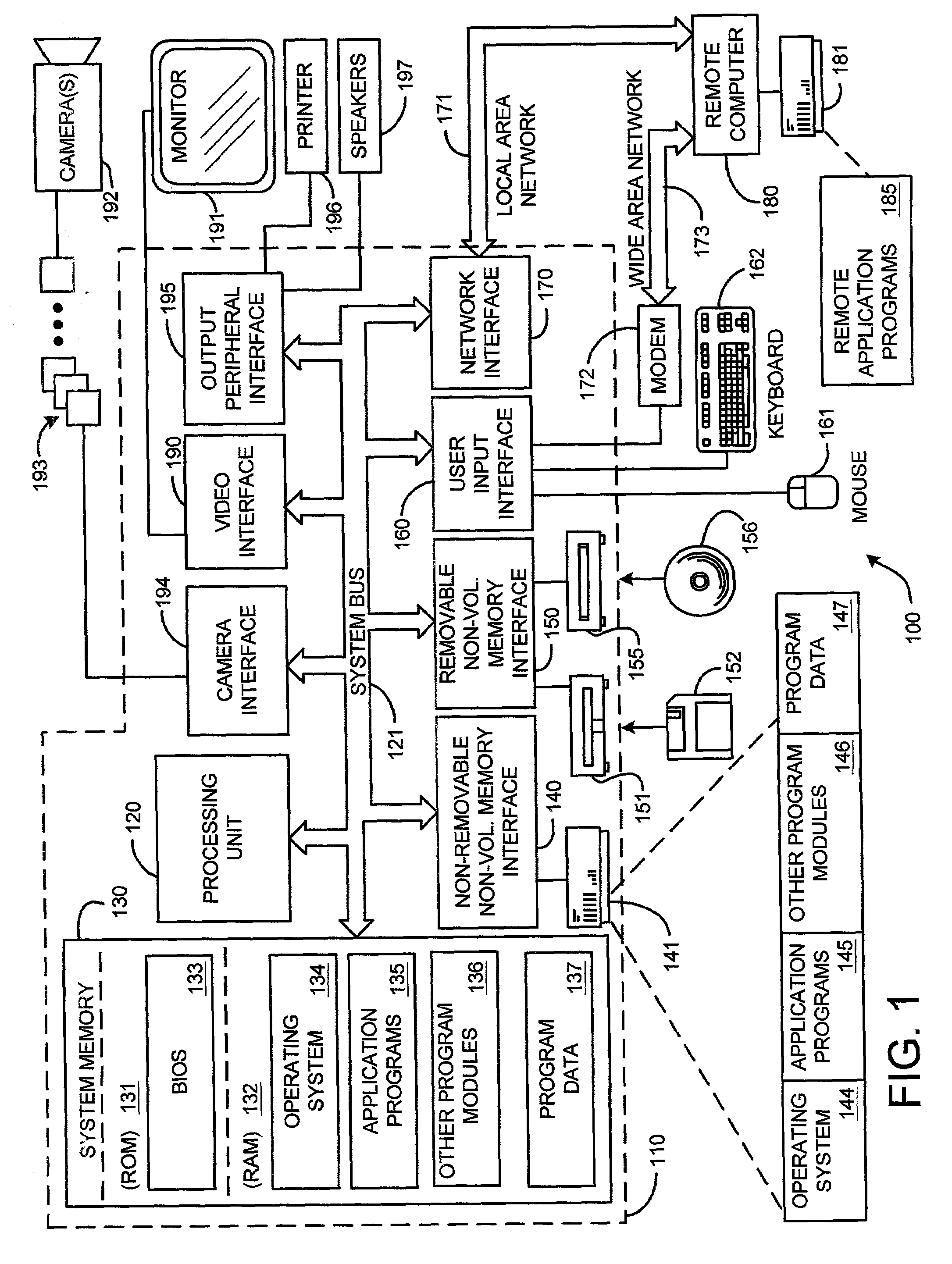
[0033]FIG. 1 illustrates an example of a suitable computing system environment 100 on which the invention may be implemented. The computing system environment 100 is only one example of a suitable computing environment and is not intended to suggest any limitation as to the scope of use or functionality of the invention. Neither should the computing environment 100 be interpreted as having any dependency or requirement relating to any one or combination of components illustrated in the exemplary operating environment 100.

[0034]The inve...


PUM


Abstract

A system and method for deghosting mosaics provides a novel multiperspective plane sweep approach for generating an image mosaic from a sequence of still images, video images, scanned photographic images, computer generated images, etc. This multiperspective plane sweep approach uses virtual camera positions to compute depth maps for columns of overlapping pixels in adjacent images. Object distortions and ghosting caused by image parallax when generating the image mosaics are then minimized by blending pixel colors, or grey values, for each computed depth to create a common composite area for each of the overlapping images. Further, the multiperspective plane sweep approach described herein is both computationally efficient, and applicable to both the case of limited overlap between the images used for creating the image mosaics, and to the case of extensive or increased image overlap.

Description

BACKGROUND[0001]1. Technical Field[0002]The invention is related to a system for mosaicing images, and in particular, to a system and method for minimizing object distortions and ghosting caused by image parallax.[0003]2. Related Art[0004]In general, image mosaics are a combination of two or more overlapping images that serve to present an overall view of a scene from perspectives other than those of the individual images used to generate the mosaic. In other words, image-based rendering techniques such as the creation of image mosaics are used to render photorealistic novel views from collections of real or pre-rendered images which allow a user or viewer to look in any desired direction. Such novel views are useful for virtual travel, architectural walkthroughs, video games, or simply for examining a scene or area from perspectives not originally captured or otherwise rendered. Typically, better final mosaicing results for a given scene or area are achieved by using many overlappi...

Claims


Application Information

Patent Timeline
Patent Type & Authority Patents(United States)
IPC IPC(8): G06K9/32G06T5/00G06T7/00G06T11/60G06T15/50G06V10/24
CPCG06K9/32G06T7/0024G06T5/20G06T11/60G06T15/503G06T5/003G06T7/0065G06K2009/2045G06T3/00G06T7/30G06T7/55G06V10/16G06V10/24
Inventor KANG, SING BINGSZELISKI, RICHARD S.UYTTENDAELE, MATTHEW T.
Owner MICROSOFT TECH LICENSING LLC
Why Eureka
Try Eureka