Optical modeling method

a technology of optical modeling and exposure region, applied in the field of optical modeling method, can solve the problem of difficulty in obtaining sufficient effects by the exposure region divided into the plurality of pixels, and achieve the effect of high accuracy

Inactive Publication Date: 2006-02-28
FUJIFILM HLDG CORP +1
View PDF12 Cites 35 Cited by
  • Summary
  • Abstract
  • Description
  • Claims
  • Application Information

AI Technical Summary

Benefits of technology

[0009]In view of the aforementioned facts, an object of the present invention is to provide an optical modeling method in which distortion of an object to be optically modeled can be inhibited, and modeling with high accuracy is made possible.

Problems solved by technology

However, if the number of neighboring pixels less than a predetermined number exceeds 75% of the total number of the pixels in the region to be exposed, it is difficult to obtain sufficient effects by the exposure region divided into the plurality of the pixels.

Method used


Image

  • Optical modeling method
  • Optical modeling method
  • Optical modeling method

Examples


first embodiment

[0040]In a first embodiment of the present invention, an exposure region on a surface of a photo-curable resin layer is divided into a plurality of pixels. The plurality of the pixels is exposed such that two neighboring pixels or more are not exposed at one time. Thereafter, unexposed pixels are exposed such that two neighboring pixels or more are not exposed at one time. By exposing the resin twice, the photo-curable resin is cured in an amount of one layer so that a plate-shaped object to be optically modeled is obtained.

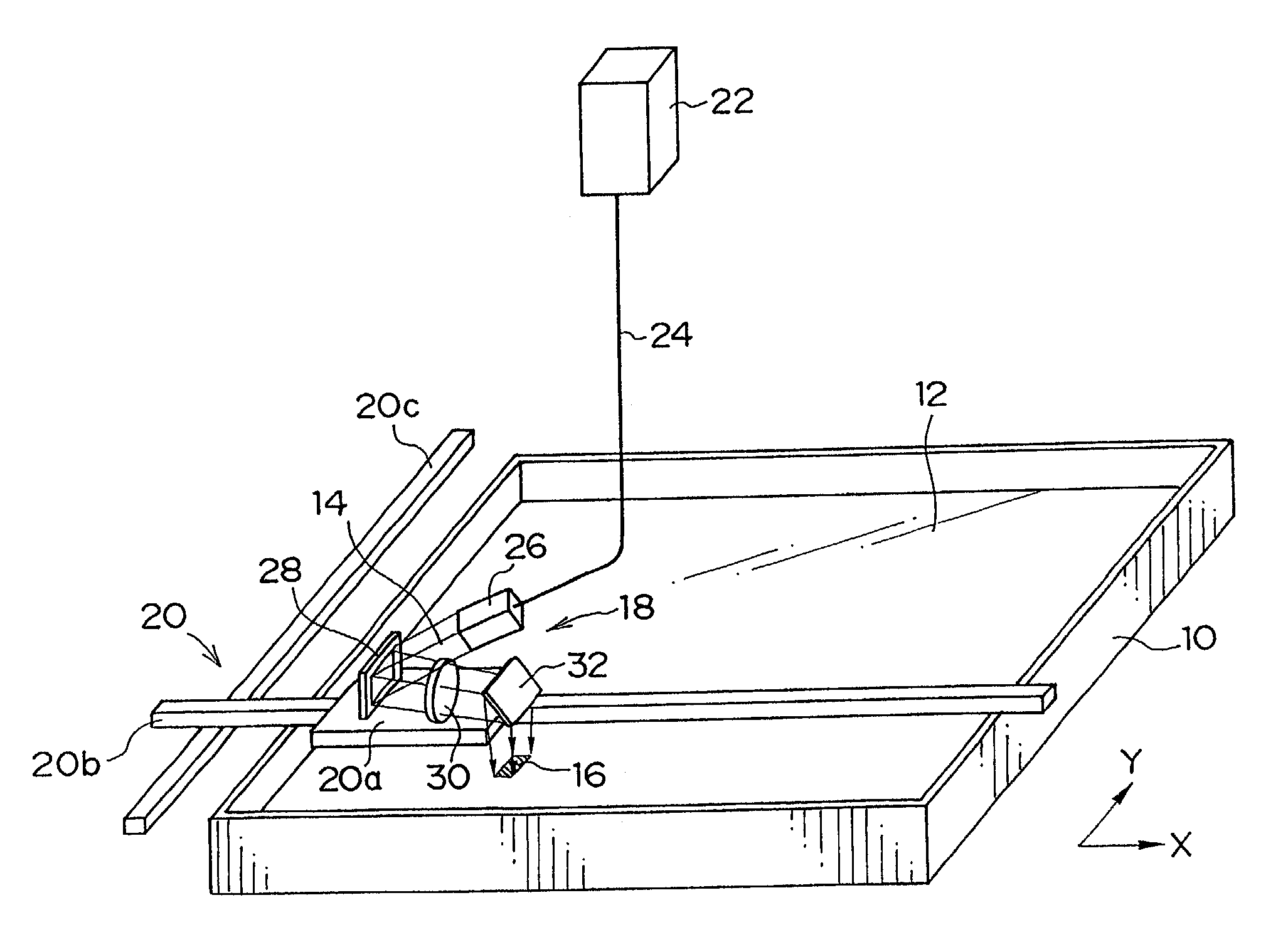
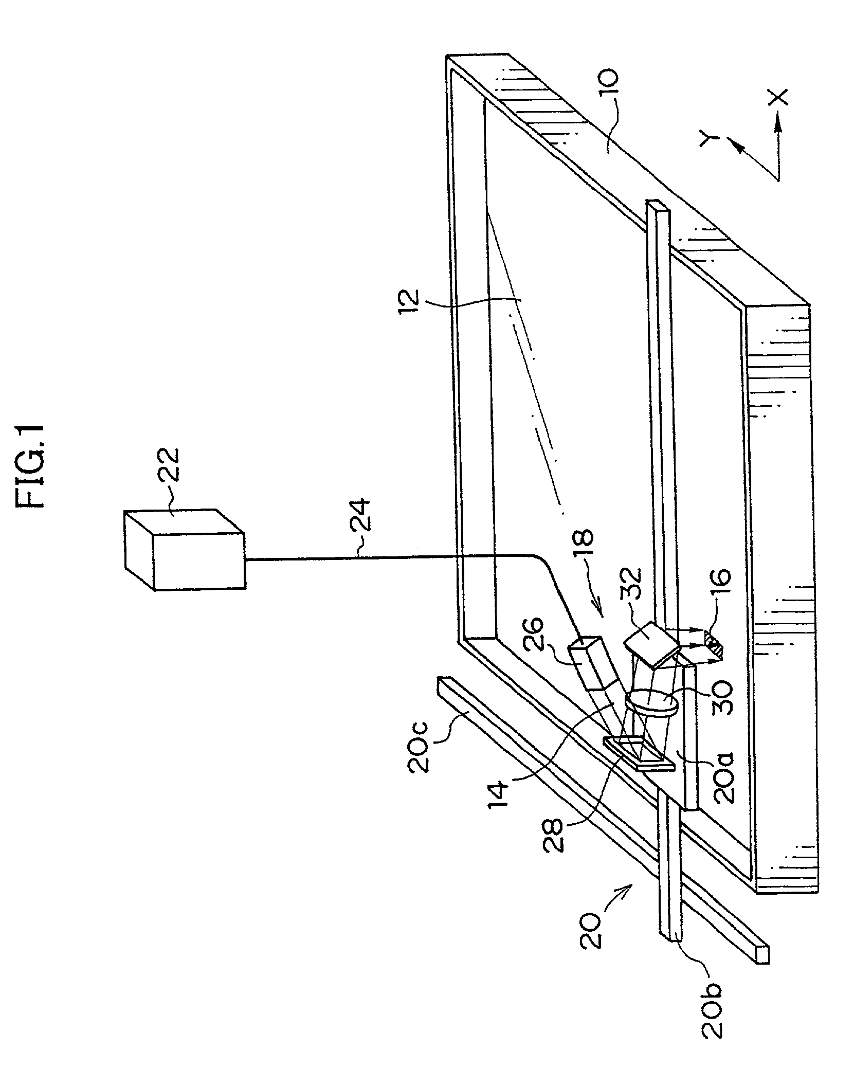
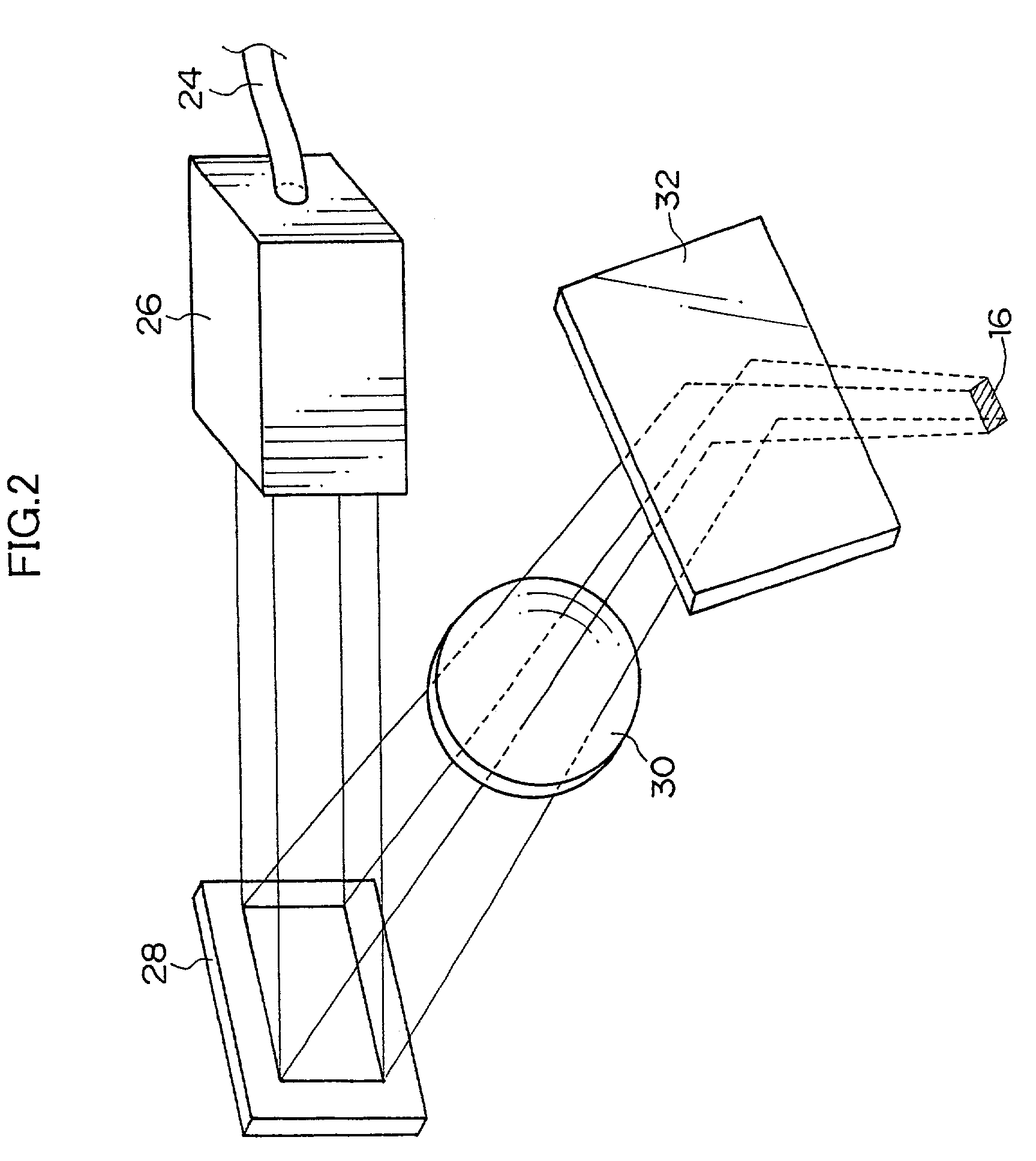
[0041]A description of an example of an optical modeling device for carrying out the optical modeling method according to the present embodiment will be given, hereinafter. As shown in FIG. 1, the optical modeling device comprises a container 10 which is opened at the upper portion thereof and which contains therein a liquid type photo-curable resin 12. An exposure unit 18, which exposes a region 16 having a predetermined area and including a plurality of pixels ...

second embodiment

[0063]In a second embodiment of the present invention, the exposure region is divided into a plurality of pixels. The plurality of the pixels are exposed such that three neighboring pixels or more are not exposed at one time. Thereafter, unexposed pixels are exposed such that three neighboring pixels or more are not exposed at one time. By exposing the photo-curable resin twice, the resin is cured by an amount of one layer so that a plate-shaped object to be optically modeled is obtained. Further, the optical modeling device that is the same as that in the first embodiment of the present invention is also used in the present embodiment.

[0064]As shown in FIG. 6, the exposure region 16 is divided into a plurality of pixels. The plurality of the pixels are divided into a first group comprising pixel sub-groups 106 each having two pixels neighboring in one direction, and a second group comprising pixel sub-groups 108 each having two pixels neighboring in the same direction as the one di...

third embodiment

[0075]In a third embodiment of the present invention, the exposure region is divided into a plurality of pixels. The plurality of the pixels are exposed such that 26 neighboring pixels or more are not exposed at one time (namely, 25 pixels (i.e., 5×5=25) are exposed at one time). Thereafter, unexposed pixels are exposed at one time, and by exposing the resin twice, the photo-curable resin is cured in an amount of one layer, whereby a plate-shaped object to be optically modeled is obtained. Further, also in the third embodiment of the present invention, the optical modeling device which is the same as that in the first embodiment of the present invention, is used.

[0076]As shown in FIG. 10, the exposure region 16 is divided into a plurality of pixels. The plurality of the pixels are further divided into a first group formed by pixel sub-groups 124 comprising 25(5×5) neighboring pixels and a second group formed by a single pixel sub-group 126 comprising the entire remaining pixels neig...


PUM

PropertyMeasurementUnit
areaaaaaaaaaaa
diameteraaaaaaaaaa
reflectanceaaaaaaaaaa

Abstract

The present invention provides an optical modeling method capable of inhibiting distortion in an object to be modeled and modeling with higher precision. A square exposure region is divided into a plurality of pixels which are further divided into first and second pixel sub-groups, the first pixel sub-group is exposed such that neighboring pixels or more are not exposed at one time, and then unexposed pixels incorporated in the second pixel sub-group are exposed two neighboring pixels or more are not exposed at one time. A photo-curable resin is exposed twice, and then cured in an amount of one photo-curable resin layer. Accordingly, the neighboring pixels are not exposed at one time, the producing of curing shrinkage is limited within one pixel, and distortion due to the curing shrinkage does not spread to the pixels neighboring the one pixel, whereby distortion in the object to be modeled can be inhibited significantly, and modeling with higher precision is made possible.

Description

BACKGROUND OF THE INVENTION[0001]1. Field of the Invention[0002]The present invention relates to an optical modeling method, and more particularly to an optical modeling method in which a three-dimensional model is created by exposing a photo-curable resin to a light beam.[0003]2. Description of the Related Art[0004]Recently, with the spread of three-dimensional computer-aided design (CAD) systems, an optical modeling system has come into general use in which a three-dimensional form is created in a virtual spacing on a computer, a photo-curable resin is exposed with a light beam on the basis of CAD data of the three-dimensional object, and is modeled to an actual three-dimensional model by using the three-dimensional CAD system. The optical modeling system comprises the steps of creating a plurality of cross sectional data by slicing CAD data at regular spacings; hardening the photo-curable resin into layers by scanning the surface of a liquid type photo-curable resin with the irra...

Claims


Application Information

Patent Timeline
Patent Type & Authority Patents(United States)
IPC IPC(8): G06F19/00B29C67/00
CPCB29C67/007B29C64/129B33Y50/02
Inventor NAGANO, KAZUHIKOOKAZAKI, YOJI
Owner FUJIFILM HLDG CORP
Why Eureka
Try Eureka