

Driving assist system for vehicle
a technology for driving assistance and vehicles, applied in repeater circuits, instruments, tractors, etc., can solve problems such as difficulty in advising drivers in a manner
- Summary
- Abstract
- Description
- Claims
- Application Information
AI Technical Summary
Benefits of technology
Problems solved by technology
Method used
Image

Examples
first embodiment
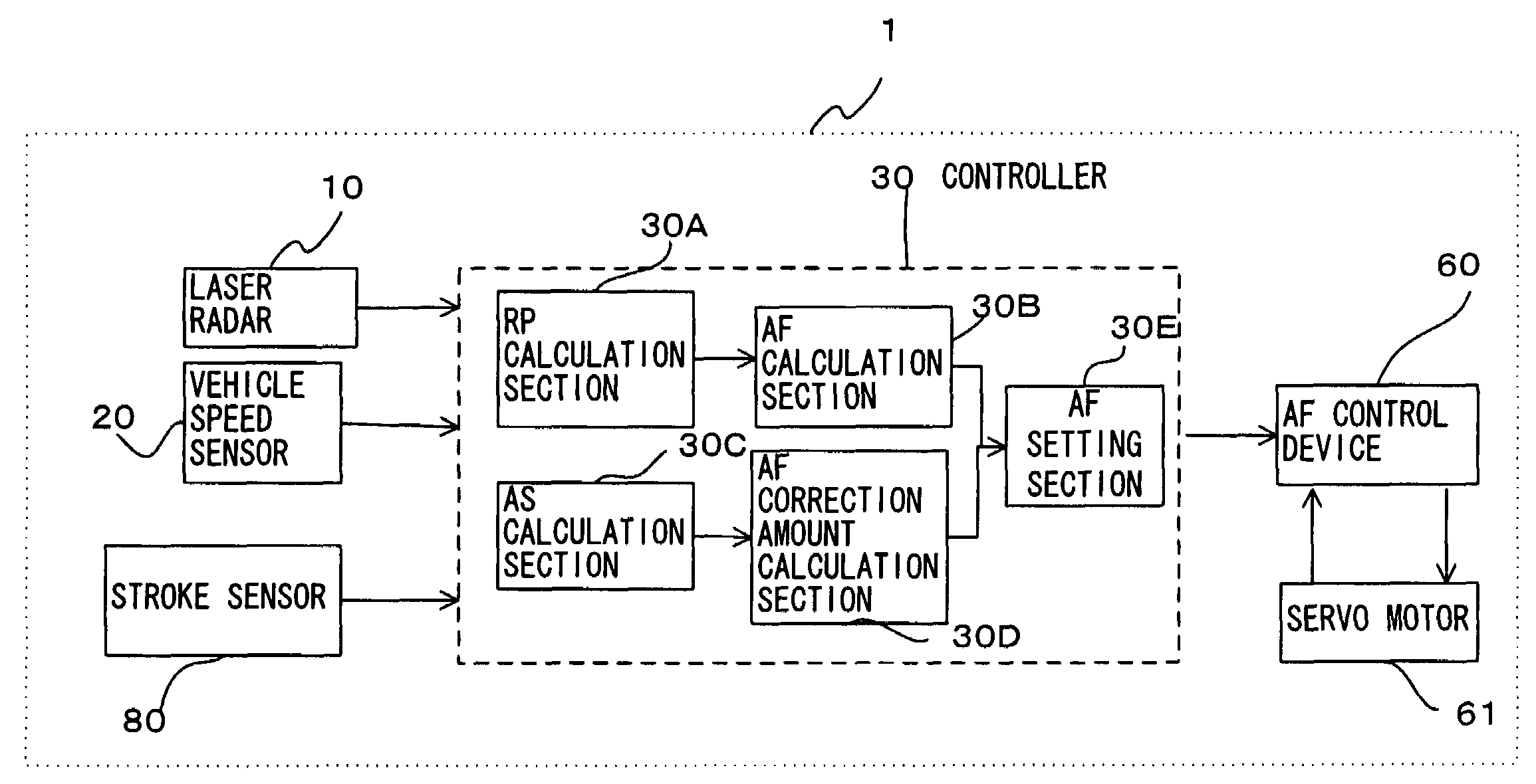
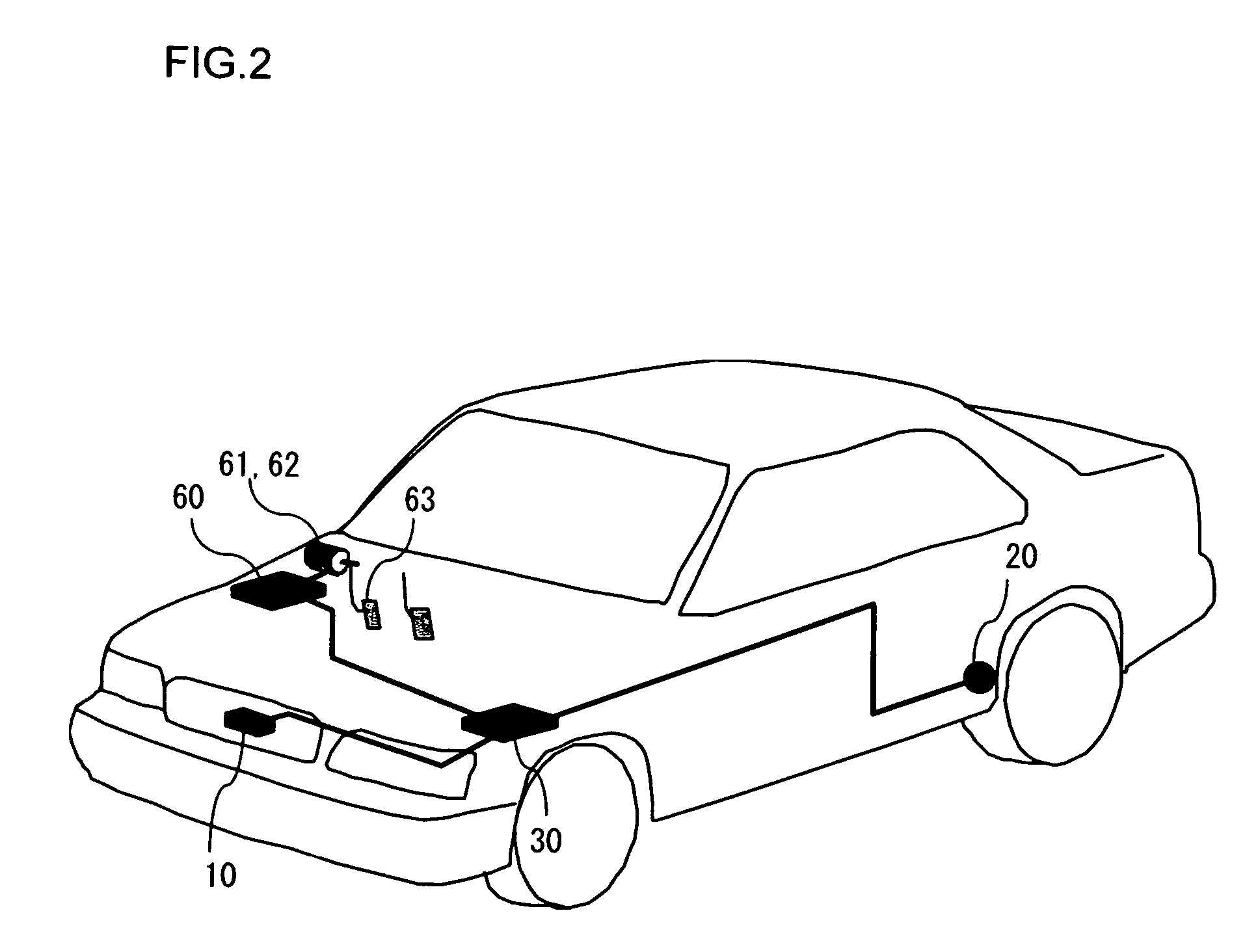
[0026]A vehicle driving assist system according to a first embodiment of the present invention will be described referring to the drawings. FIG. 1 shows the structure of a vehicle driving assist system 1 of the first embodiment, and FIG. 2 is a structural diagram of a vehicle fitted with the vehicle driving assist system 1. FIG. 3 is a structural diagram of an accelerator pedal and the vicinity thereof.
[0027]First of all, the structure of the vehicle driving assist system will be described.
[0028]A laser radar 10 is attached to a front grill of the vehicle or to a bumper etc., and propagates infrared pulses in a forward horizontal direction for scanning. The laser radar 10 measures reflected radiation of infrared pulses reflected by a plurality of reflecting objects ahead, such as the rear of a vehicle in front, and detects distance (vehicle distance) from the subject vehicle to a preceding vehicle and relative velocity (relative speed) of vehicles based on the elapsed time the refle...
first embodiment modification 2
[0080]FIG. 9 shows another example of a map of the AF correction amount ΔF(Vp) with respect to the accelerator pedal operating speed Vp.
[0081]The map of FIG. 9 includes an unchanging region where the AF correction amount ΔF(Vp) does not vary even if the operating speed Vp changes, within a region where the accelerator pedal operating speed Vp is small. More particularly, as shown in FIG. 9, a range of the accelerator pedal operating speed Vp from 0 to the predetermined value Vp0 (0≦Vp≦Vp0) is taken as the unchanging region. In addition, a slope of the AF correction amount ΔF(Vp) when depressing the accelerator pedal 63 (Vp>Vp0) is set to be larger than a slope of the amount ΔF(Vp) when holding or releasing the accelerator pedal 63.
[0082]Since the unchanging region is included in the map of the AF correction amount ΔF(Vp), the accelerator pedal reaction force F does not vary needlessly in response to slight change in the pedal operating speed Vp when holding the accelerator pedal 63 ...
second embodiment
[0083]Next, a vehicle driving assist system according to a second embodiment of the present invention will be described.
[0084]The structure of the vehicle driving assist system of the second embodiment is identical to that of the first embodiment, and thus, its explanation is omitted. Here, explanation will focus on points that differentiate the second embodiment from the first embodiment.
[0085]In the second embodiment, only the processing of the AF correction amount calculation in step S109 in the flow chart of FIG. 6 differs from the first embodiment described above. In the first embodiment, the accelerator pedal reaction force F was corrected, taking account of the pushing-back force that the driver perceives when operating the accelerator pedal 63. In the second embodiment, the accelerator pedal reaction force F will be corrected, taking account of driver's sensitivity to the accelerator pedal reaction force F when operating the accelerator pedal 63.
[0086]When operating the acce...
PUM
 Abstract
Description
Claims
Application Information