Features for thin composite architectural panels

a composite architectural panel and composite technology, applied in special buildings, parkings, walls, etc., can solve the problems of manufacturing limitations, prone to represent rather cumbersome and costly processes, and manufacturing costs, and achieve the effect of altering coloring or other visual features

Inactive Publication Date: 2006-03-07
CENTRIA
View PDF28 Cites 93 Cited by
  • Summary
  • Abstract
  • Description
  • Claims
  • Application Information

AI Technical Summary

Benefits of technology

[0010]There is also broadly contemplated, in accordance with another embodiment of the present invention, the use of interchangeable laminate components in affording the capability of altering the coloring or other visual features of a reveal in a panel or panels.
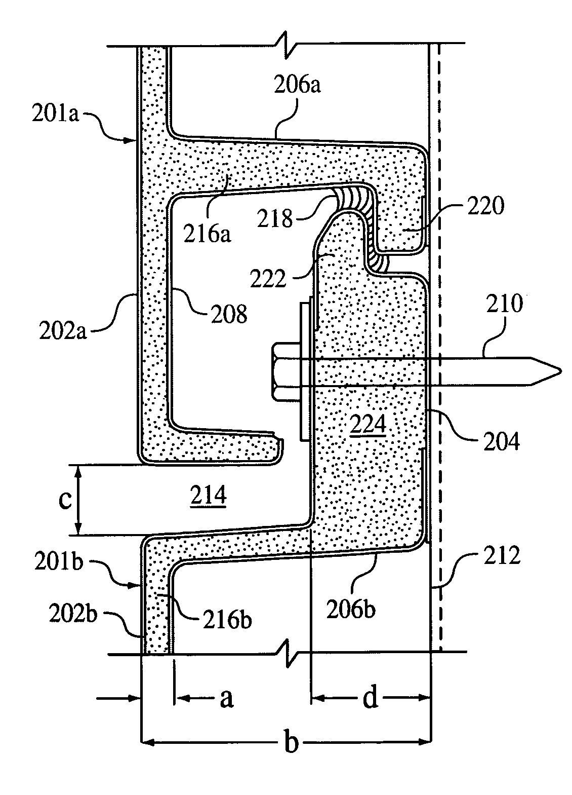
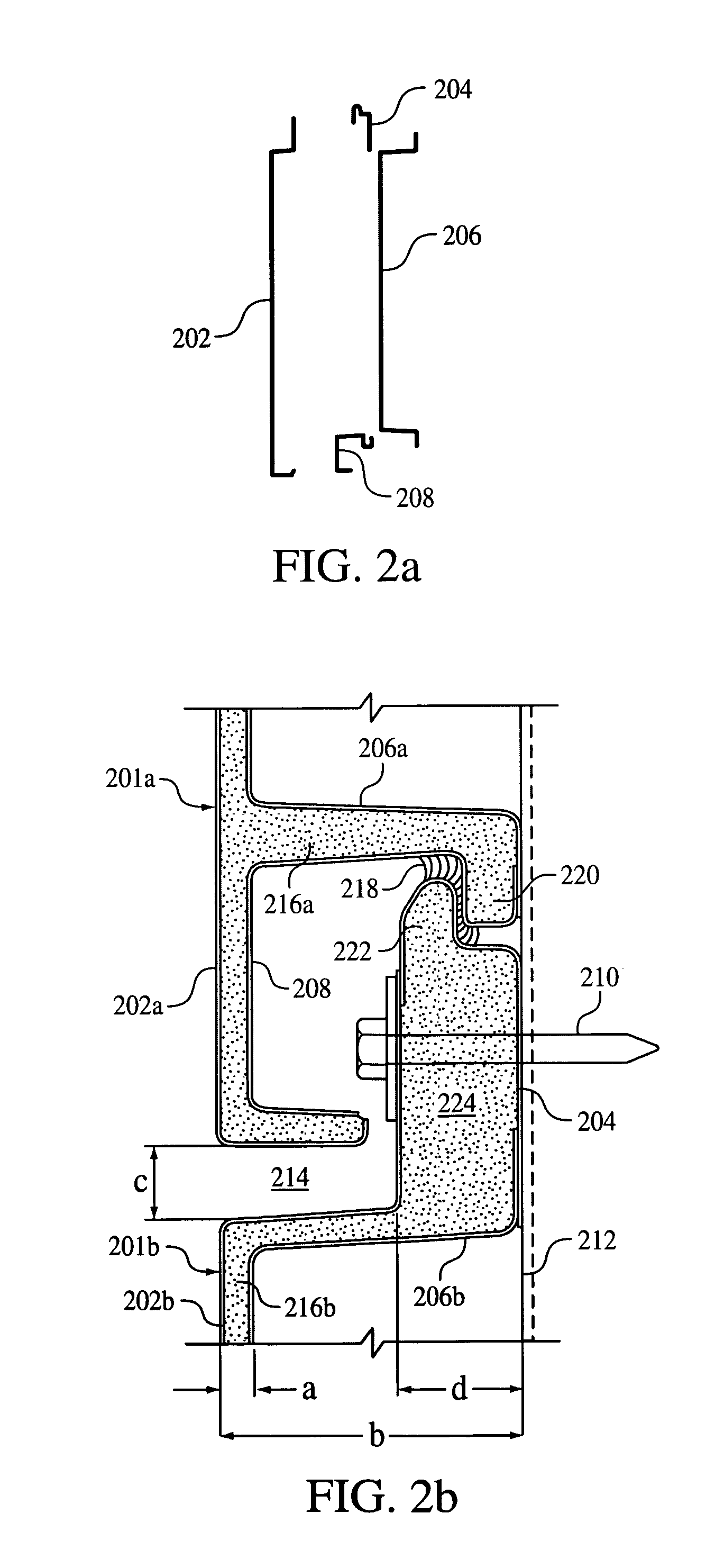
[0011]Generally, there is broadly contemplated in accordance with at least one presently preferred embodiment of the present invention a thin composite architectural panel comprising: a structural core; a set of laminates disposed about the structural core; a first portion for interfacing and facilitating interconnection with another thin composite architectural panel; a second portion for interfacing and facilitating interconnection with another thin composite architectural panel; the first interfacing portion comprising a first lip portion adapted to be interposed between a wall and a lip portion of another thin composite architectural panel in a building wall assembly; and the second interfacing portion comprising a second lip portion adapted to flank, with a wall, a lip portion of another thin composite architectural panel in a building wall assembly; whereby the introduction of a sealant between the first lip portion and a lip portion of another thin composite architectural panel is facilitated; whereby the introduction of a sealant between the second lip portion and a lip portion of another thin composite architectural panel is facilitated.

Problems solved by technology

All of this tends to represent rather cumbersome and costly processes.
Attendant manufacturing processes tend to be quicker and can involve lower manufacturing costs than with the conventional thin composite processes described above, but here manufacturing limitations do exist.

Method used


Image

  • Features for thin composite architectural panels
  • Features for thin composite architectural panels
  • Features for thin composite architectural panels

Examples


Embodiment Construction

[0022]As touched upon heretofore, thin composite architectural panels, also known as thin composite wall panels, are recognized in the art as normally encompassing a laminated composite including a polymeric or foam core sandwiched between two laminates, e.g., metal skins.

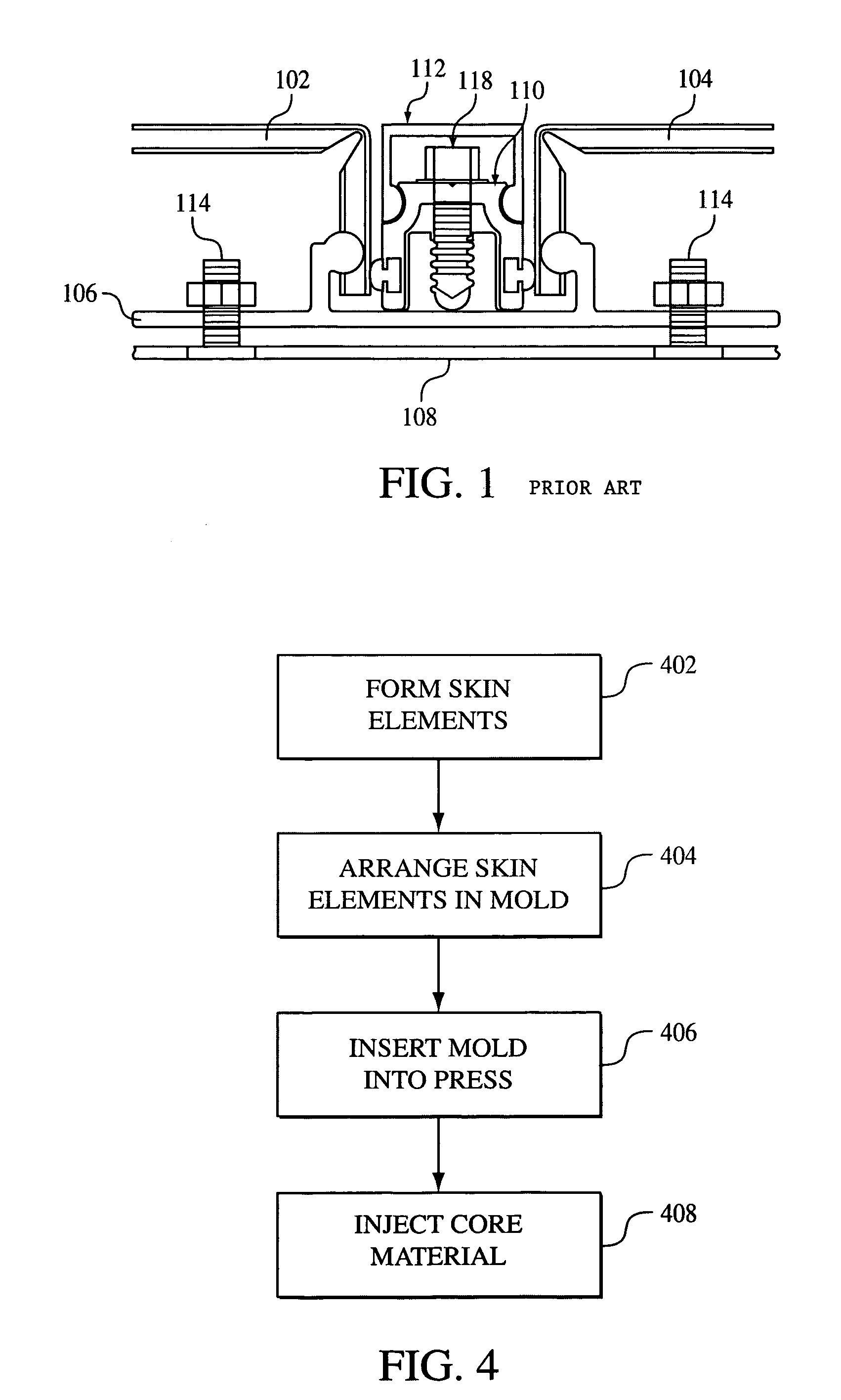
[0023]Conventionally, sheets of a thin composite are fabricated by cutting them to size and bending their ends at right angles via routing. The panels are typically adjoined to one another, between bent ends, via extruded joining mechanisms. Shown in FIG. 1 is such a conventional arrangement. As shown, two bent vertical thin composite panels 102 and 104 are joined at a vertical joint via an extruded connector indicated at 106. (The relatively small thickness dimension of the panels 102 and 104 is to be noted, as starkly opposed to “thick” building panels whose thickness may extend, e.g., all the way back to a building structure as indicated at 108.) Other components that may typically be provided include a pressure...


PUM


Abstract

Thin composite panels with interconnection schemes that are unitized with the panels, i.e., formed integrally and substantially simultaneously with the panels. Further contemplated is the application of an injection molding technique, such as reaction injection molding, in establishing a foam or polymeric core between laminates in thin composite panels. Additionally contemplated is the use of interchangeable laminate components in affording the capability of altering the coloring or other visual features of a reveal in a panel or panels.

Description

FIELD OF THE INVENTION[0001]The present invention generally relates to thin composite architectural panels, and methods of making and assembling the same.BACKGROUND OF THE INVENTION[0002]To date, thin composite architectural wall panels have been manufactured in multi-step processes which often involve both sheet manufacturers and panel fabricators. First, a thin composite sheet is manufactured by laminating metal skins to a plastic core. (An example of such a composite sheet is the “ALUCOBOND” material produced by Alusuisse Group, Ltd., Zurich, Switzerland.) Next, these sheets are typically shipped to a fabricator where they are cut to size and routed so as to return the edges around the perimeter. Typically, extrusions are fabricated and applied to the panel perimeter to create panel joinery. Also, stiffeners are typically applied in the field (i.e., the major flattened portion) of the panel to reduce the bowing of the thin panel under load. All of this tends to represent rather c...

Claims


Application Information

Patent Timeline
Patent Type & Authority Patents(United States)
IPC IPC(8): E04C1/00E04B2/08E04B2/30E04C2/292E04F13/08E04F13/12E04F19/02
CPCE04C2/292E04F13/12E04F13/0878E04F19/02
Inventor BOYER, KEITH
Owner CENTRIA
Why Eureka
Try Eureka