
Snap-in-place building block

a technology of building blocks and building blocks, applied in the field of building materials, can solve the problems of increasing construction costs, requiring a great deal of time and skill, and presenting a very pleasant appearance, so as to reduce the time and cost of construction

Inactive Publication Date: 2006-03-07
KELLEY JAY R
View PDF41 Cites 58 Cited by
  • Summary
  • Abstract
  • Description
  • Claims
  • Application Information

AI Technical Summary

Benefits of technology

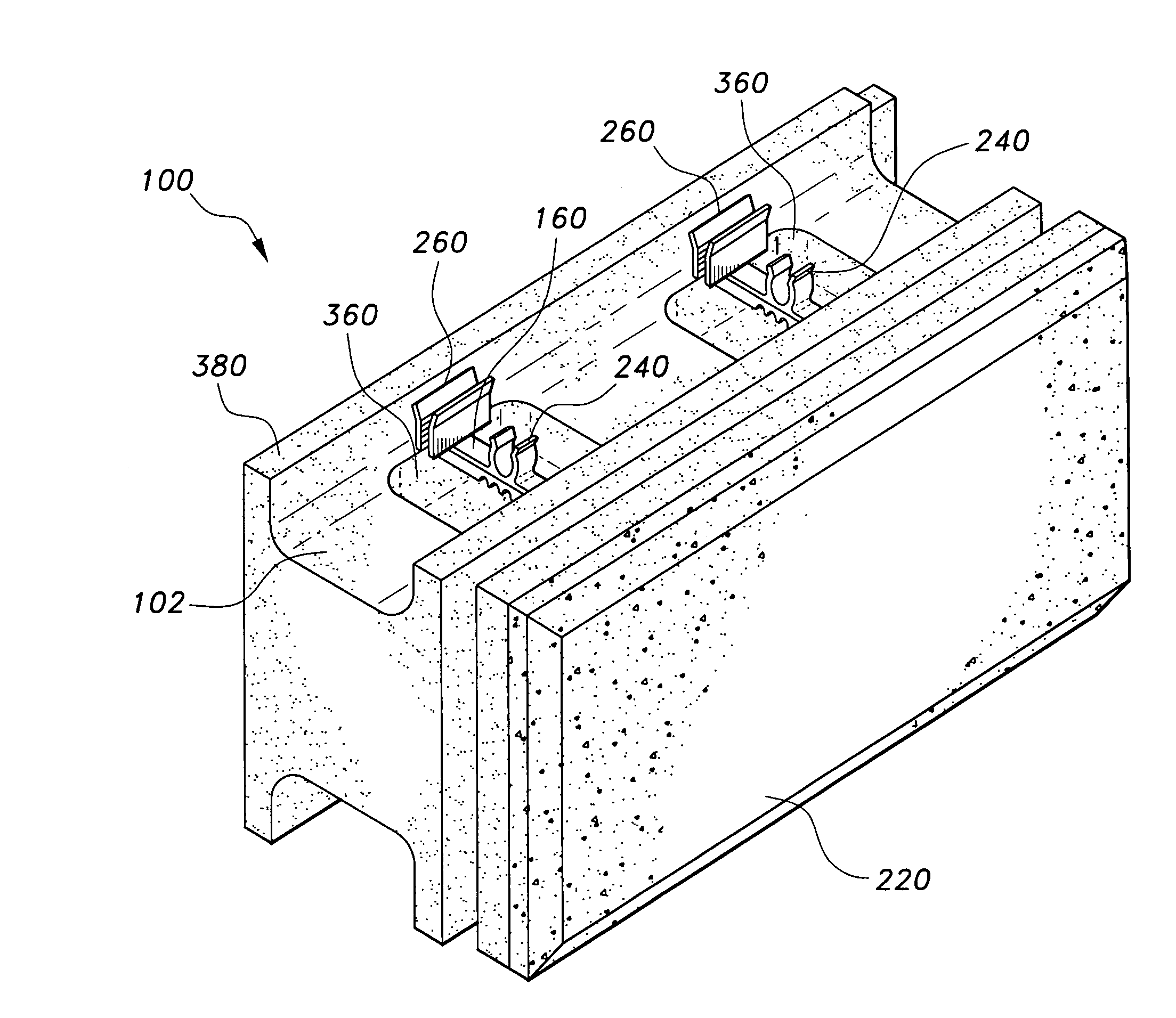
[0007]The snap-in-place building block incorporates several features into a single building block that reduces the time and cost of constructing a wall. The snap-in-place building block has three primary components. The first component is two internal support brackets constructed from durable plastic that are equipped with male and female interlocking devices, a rebar clip, a furring strip, and exterior flanges for the attachment of a veneer.
[0011]By constructing the body of the snap-in-place building block out of foamed plastic, the body acts both as thermal insulation and as a vapor barrier, thereby eliminating the high costs of wall insulation. The snap-in-place building block is intended to be used so that the veneer faces outward to the environment. The interior side of the block is equipped with a furring strip that acts as a wall stud for the attachment of an interior wall system.

Problems solved by technology

In this manner a block wall is constructed, but to achieve a block wall that is both level and plumb, a great deal of time and skill is required.
The time and skill required to build a concrete block wall raises construction costs.
Another problem with concrete block walls is that in their unfinished state they do not present a very pleasant appearance and therefore require finishing.
The finishing of a concrete block wall also requires considerable skill and can add substantial cost to construction.
This has not been found to be an effective solution for concrete blocks because the grooves and protrusions cannot be formed to precise enough tolerances during manufacturing.
That means the blocks must be modified by hand, which greatly detracts from their cost effectiveness.
The problem of adding siding or veneers to building blocks has also not been adequately addressed.
Block wall systems exist that may have veneers or siding attached, but none currently exist that have an exterior veneer integrated into the block itself.

Method used


Image

  • Snap-in-place building block
  • Snap-in-place building block
  • Snap-in-place building block

Examples


Embodiment Construction

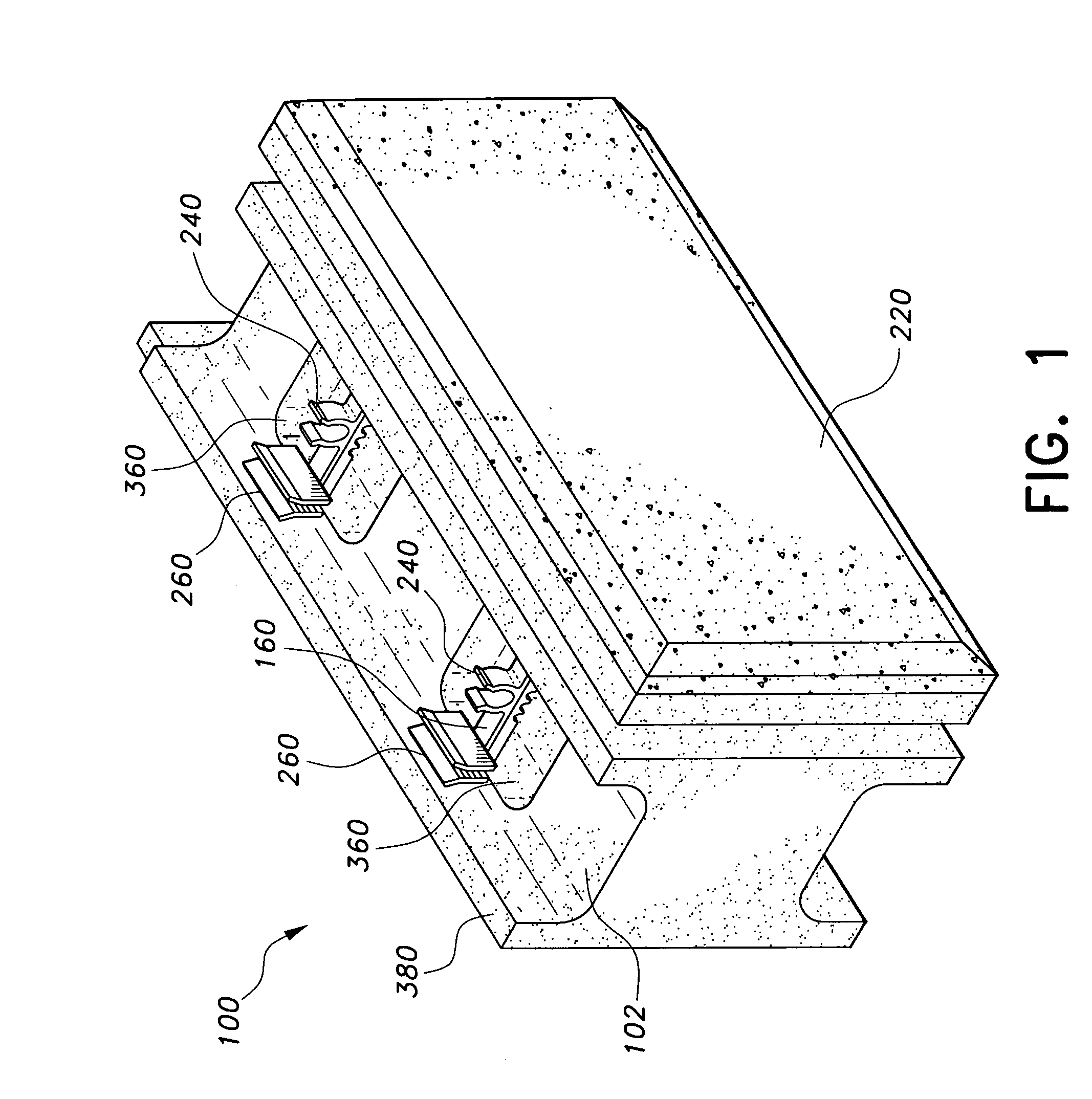
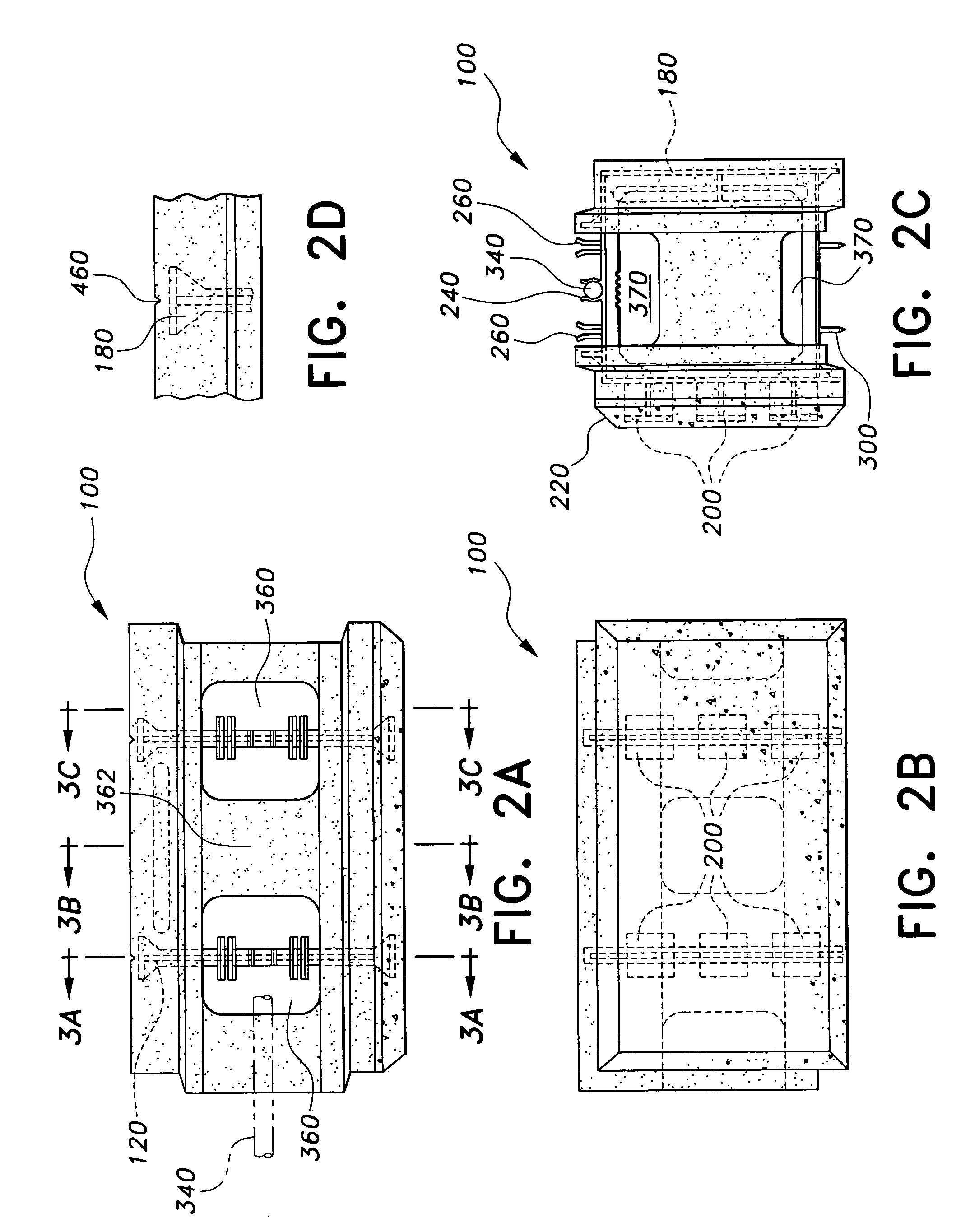
[0042]The present invention is a snap-in-place building block, designated generally as 100 in the drawings, also referred to herein as a “building block.”FIG. 1 shows a perspective view of the snap-in-place building block 100. The snap-in-place building block 100 is made up of several components to form a single unit as shown in FIG. 1. The first of the components making up the snap-in-place building block 100 is an internal support bracket, designated generally as 120 and shown in a perspective view in FIGS. 11 and 12, and in greater detail in FIGS. 10A–F.

[0043]The internal support bracket 120 is made of durable plastic, preferably by injection molding. The internal support bracket 120 comprises a generally rectangular open frame 140 surrounded by a flange 160. The flange 160 has a top, bottom, right side and left side. The left side of the flange 160 is wider than the other three sides of the flange 160 and forms a furring strip 180 that acts as a wall stud for the attachment of g...


PUM


Abstract

The snap-in-place building block has two internal support brackets constructed from durable plastic that are equipped with male and female interlocking devices, a rebar clip, a furring strip, and exterior flanges that are molded into a block body made from foamed plastic. A body of foamed plastic is molded around the brackets, the body defining two hollow cores, one bracket being disposed in each of the cores. A horizontal channel is formed between adjacent blocks when stacked above each other. The cores and horizontal channels receive concrete or mortar that forms vertical columns and horizontal beams within the wall. An exterior veneer is attached to the protruding exterior flanges on one side of the building block. The configuration of the block may be altered to allow for half-blocks and corner blocks.

Description

BACKGROUND OF THE INVENTION[0001]1. Field of the Invention[0002]The present invention relates to building materials, and particularly to a snap-in-place building block with a molded in place exterior veneer that can self-level and self-plumb.[0003]2. Description of the Related Art[0004]Walls for homes, schools, hospitals and other residential and commercial buildings are constructed from a variety of materials, such as wood, brick, synthetic materials, stone and concrete blocks. Concrete block construction is conventionally done with hollow cored cement masonry units (“CMU's”). The CMU's are typically sealed in place with mortar so that the hollow cores of the CMU's face upwards. The hollow cores are sometimes filled with insulation, concrete, rebar, or some other type of filler.[0005]In concrete block construction, a foundation is laid and then a row, called a “course,” of concrete blocks are set in mortar on the foundation. Another layer of mortar is placed on top of the fist cour...

Claims


Application Information

Patent Timeline
IPC IPC(8): E04C2/04
CPCE04B2/16E04B2002/0269E04B2002/0232E04B2002/0208
Inventor KELLEY, JAY R.
Owner KELLEY JAY R
Learn More