
Pair of opposed co-operating refining elements

a technology of co-operating refining elements and opposed parts, which is applied in the field of disintegration and refining of lignocellulosic materials, can solve the problems of large amount of energy required to achieve this work, disturbance of fiber flow, uneven pulp quality, etc., and achieves the effect of reducing disturbances in fiber flow, improving pulp quality, and improving quality

Inactive Publication Date: 2006-03-07
VALMET TECH INC
View PDF9 Cites 2 Cited by
  • Summary
  • Abstract
  • Description
  • Claims
  • Application Information

AI Technical Summary

Benefits of technology

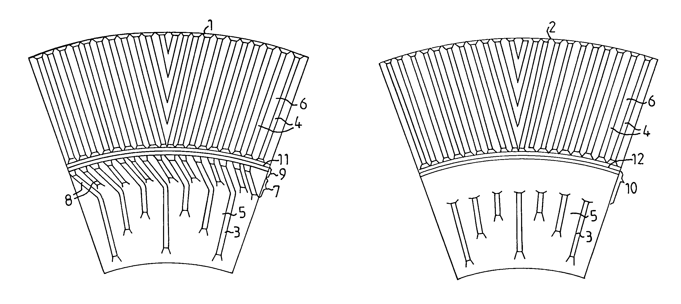
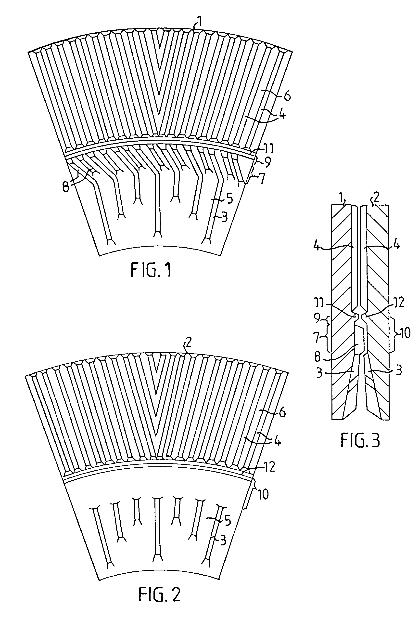
[0013]In accordance with the present invention, the refining elements are formed so, that the main part of the steam generated in the refining gap is prevented from flowing rearwardly inward in the refining gap, but instead flows forwardly outward. This is achieved by the bars of the refining elements being formed in such a way that the material in the refining gap forms a steam lock, which moves the pressure maximum inward in the refining gap. Due to the fact that the main part of the steam flows outward together with the material, disturbances in the fiber flow are minimized, and the quality of the pulp will be higher and more uniform.

Problems solved by technology

Large amounts of energy are required to achieve this working.
The rearward flowing steam causes a disturbance in the fiber flow in the refining gap.
This is inconvenient, because a non-uniform fiber flow results in uneven pulp quality.

Method used


Image

  • Pair of opposed co-operating refining elements
  • Pair of opposed co-operating refining elements

Examples


Embodiment Construction

[0018]Each of the opposed co-operating refining elements, 1 and 2, according to the present invention consists of a single element, which extends radially along the entire refining gap, or of at least two partial elements, each of which extends radially, one after the other, along a portion of the refining gap.

[0019]Each of the refining surfaces of the co-operating refining elements, 1 and 2, is provided with bars, 3 and 4, and intermediate grooves, 5 and 6. The first refining element 1, which is intended to be placed on a rotary refining disk, is formed with a first radially restricted zone 7 with elevated bars 8 located in the inner portion of the refining gap. Directly outside this first zone 7, a second radially restricted zone 9 without bars is located. This zone 9, instead of having bars, can be formed smooth or with an uneven surface which is intended to bring about a certain braking effect on the material in the refining gap. The second refining element 2, which is intended ...


PUM

PropertyMeasurementUnit
pressureaaaaaaaaaa
angleaaaaaaaaaa
angleaaaaaaaaaa

Abstract

Apparatus for refining lignocellulosic material is disclosed having a pair of opposed co-operating refining elements intended for a disk refiner for the disintegration of the lignocellulosic material in a refining gap between two opposed counter-rotating refining disks. The refining elements are intended to be placed directly in front of each other on opposed refining disks, and both refining elements are formed with refining surfaces with bars and grooves. In order to prevent generated steam from flowing rearward in the refining gap, a first refining element is formed with a first radially restricted zone with elevated bars and a second radially restricted zone without bars directly outside the first zone. A second opposed refining element is formed with a third radially restricted zone without bars, which third zone is located directly in front of the first and the second zone on the first refining element.

Description

FIELD OF THE INVENTION[0001]The present invention relates to the disintegration and refining of lignocellulosic material, such as mechanical pulp (TMP, CTMP), reject pulp, recycled fiber pulp and the like in a disk refiner with planar or angled disks. More particularly, the present invention relates to refiner elements for use in a refiner of this kind.BACKGROUND OF THE INVENTION[0002]A disk refiner comprises two opposed counter-rotating refining disks, one or both of which are rotary within a surrounding refiner housing. A plurality of refining elements is arranged on the refining disks. A refining element can also be assembled from several partial elements. These refining elements are formed with a pattern of bars and intermediate grooves. The refining disks are located in such a way that the refining elements form a refining gap, through which, the fiber material is intended to pass from the inside out, and during that passage the disintegration is carried out by the bars of the ...

Claims


Application Information

Patent Timeline
Patent Type & Authority Patents(United States)
IPC IPC(8): B02C7/12B02C7/02D21D1/30
CPCB02C7/02D21D1/306B02C7/12
Inventor VIRVING, NILS
Owner VALMET TECH INC
Learn More