
Annular-type distributor with improved flow uniformity

a distributor and annular technology, applied in the direction of indirect heat exchangers, solid fuel combustion, lighting and heating apparatus, etc., can solve the problems of degrading heat transfer efficiency, increasing the speed of heating medium introduced into the reactor, etc., to improve flow uniformity, reduce flow rate, and improve heat transfer efficiency

Active Publication Date: 2006-11-16
LG CHEM LTD
View PDF7 Cites 2 Cited by
  • Summary
  • Abstract
  • Description
  • Claims
  • Application Information

AI Technical Summary

Benefits of technology

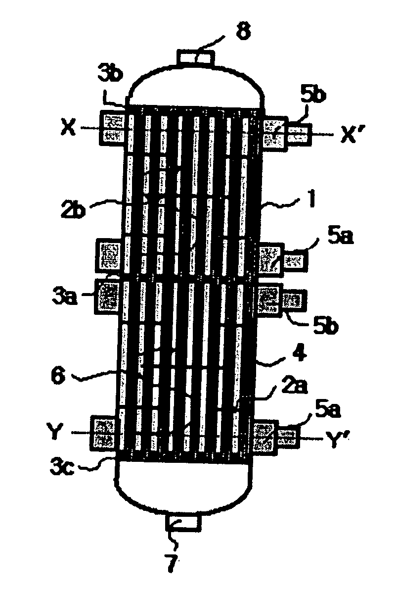
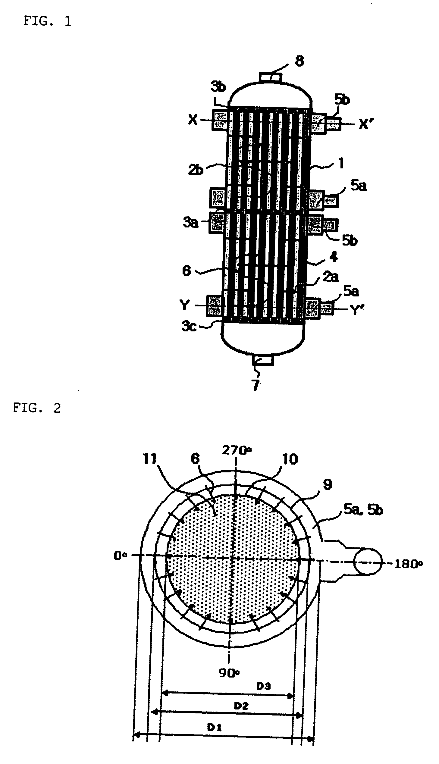
[0006] However, inventors of the present invention have found that there are limitations to distribute the heating medium with improved flow uniformity if the heating medium is fed into the conventional annular-type distributor having one slit layer through one duct, even if the number and size of the opening arrays are adjusted. In addition, in order to reduce the flow rate at a predetermined region where fluid is locally concentrated, if the size of the openings formed at the predetermined area is reduced, the speed of the heating medium introduced into the reactor may increase, so the flow of the heating medium may be disturbed in the reactor, thereby degrading the heat transfer efficiency.
[0007] In order to solve the above problem occurring in the prior art, the present invention provides an annular-type distributor capable of receiving and discharging fluid in at least two circumferential portions thereof with improved flow uniformity and / or a low fluid speed, and a reactor or a heat exchanger having the same.
[0015] The annular-type distributor according to the present invention is advantageous when uniformly feeding or discharging fluid at a low fluid speed.

Problems solved by technology

However, inventors of the present invention have found that there are limitations to distribute the heating medium with improved flow uniformity if the heating medium is fed into the conventional annular-type distributor having one slit layer through one duct, even if the number and size of the opening arrays are adjusted.
In addition, in order to reduce the flow rate at a predetermined region where fluid is locally concentrated, if the size of the openings formed at the predetermined area is reduced, the speed of the heating medium introduced into the reactor may increase, so the flow of the heating medium may be disturbed in the reactor, thereby degrading the heat transfer efficiency.

Method used


Image

  • Annular-type distributor with improved flow uniformity
  • Annular-type distributor with improved flow uniformity
  • Annular-type distributor with improved flow uniformity

Examples


embodiment 1

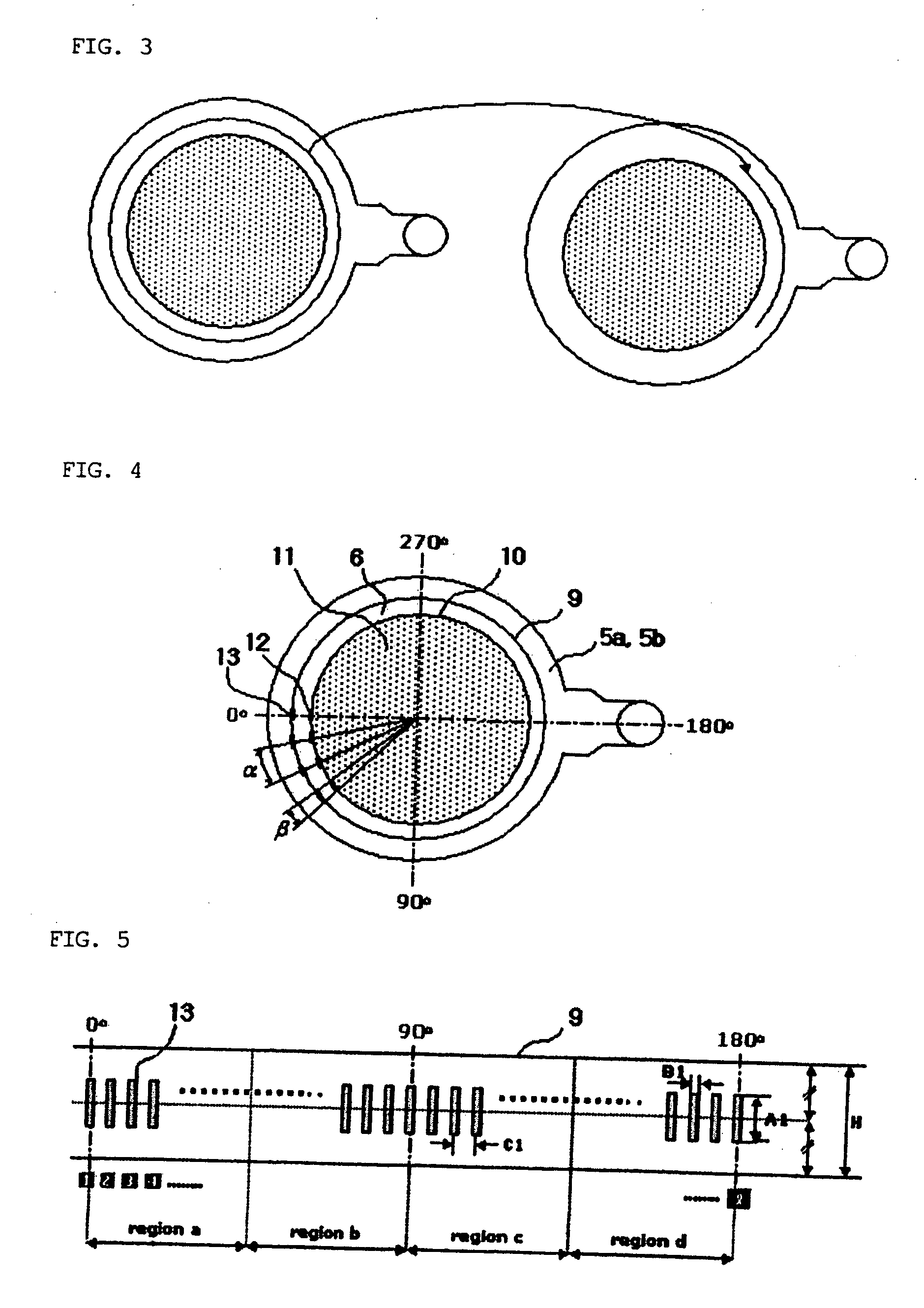
[0068] The annular-type distributor having the outer slit layer and the inner slit layer as shown in FIG. 4 was fabricated as follows:

[0069] Diameter of outer slit layer: 4550 mm

[0070] Diameter of inner slit layer: 4150 mm

[0071] Height of slit in inner slit layer: 300 mm

[0072] Width of slit in inner slit layer: 72.43 mm (β=2°)

[0073] Height of slit in outer slit layer: region a (100 mm), region b (150 mm), region c (200 mm), and region d (100-300 mm)

[0074] Width of slit in outer slit layer: 79.41 mm (β=2°)

[0075] Slit distribution in inner / outer slit layer: α=6°


PUM


Abstract

Disclosed are an annular-type distributor having a multiple slit layer including at least two annular layers, which are stacked while being spaced by a predetermined distance and in which at least one slit is formed so as to receive or discharge fluid; a reactor or a heat exchanger having the annular-type distributor; and a method of producing unsaturated aldehyde or unsaturated acid from olefin by catalytic gas phase oxidation reaction using the reactor.

Description

[0001] This application claims the benefit of the filing date of Korean Patent Application No. 10-2005-0035889, filed on Apr. 29, 2005, in the Korean Intellectual Property Office, the disclosure of which is incorporated herein in its entirety by reference. FIELD OF THE INVENTION [0002] The present invention relates to an annular-type distributor capable of receiving or discharging fluid in at least two circumferential portions thereof with improved flow uniformity and / or a low fluid speed, and a reactor or a heat exchanger having the same. BACKGROUND OF THE INVENTION [0003] In general, a multi-tubular catalytic reactor in the form of a heat exchanger is one of reactors capable of effectively removing heat derived from chemical reaction. In the multi-tubular catalytic reactor, solid catalysts are filled in a plurality of reaction tubes and reaction gas is fed into the reaction tubes, thereby generating chemical reaction in order to obtain desired products. In addition, a heating medi...

Claims


Application Information

Patent Timeline
Patent Type & Authority Applications(United States)
IPC IPC(8): B01J19/00F23B99/00
CPCB01J8/008B01J8/067B01J19/1825B01J2208/00221F28F9/0263F28D7/0066F28D7/0091F28D7/1607F28F9/02B01J2219/00099B01J8/02B01J8/06B01J8/26
Inventor SHIN, SANG BAEKHAN, SANG PHILIM, YE HOO
Owner LG CHEM LTD
Learn More