Axial-flow fan and projector provided with the same

a technology of axial flow fan and projector, which is applied in the direction of wind motor with parallel air flow, wind motor with perpendicular air flow, liquid fuel engine components, etc., to achieve the effects of preventing turbulence, reducing noise, and restrainting loss of flow ra

Inactive Publication Date: 2006-03-07
SEIKO EPSON CORP
View PDF17 Cites 26 Cited by
  • Summary
  • Abstract
  • Description
  • Claims
  • Application Information

AI Technical Summary

Benefits of technology

[0009]According to the above arrangement, since the speed of the air flowing through the axial-flow fan is accelerated and is leveled, the turbulence can be restrained. Accordingly, even when the fan is rotated at a high speed, the noise caused by the collision of the turbulence from the main fin and the auxiliary fin can be reduced, thus providing a low-noise axial-flow fan while maintaining high static pressure.
[0039]A projector according to another aspect of the present invention includes: an optical system including an optical modulator that modulates a light beam irradiated by a light source in accordance with image information to project the light beam in an enlarged manner to form a projection image and a fan for circulating air, in which the fan is the axial flow fan described above. Since the above axial-flow fan is provided on the projector, the same advantages as the axial-flow fan can be obtained.

Problems solved by technology

As described above, in order to secure the necessary flow rate and static pressure for sufficient cooling, high-speed rotation of the fan is inevitable, which result in noise.

Method used


Image

  • Axial-flow fan and projector provided with the same
  • Axial-flow fan and projector provided with the same
  • Axial-flow fan and projector provided with the same

Examples


second embodiment

[0175]Next, the present invention will be described below. Incidentally, in the following, the same reference numerals will be attached to the same components to omit the description thereof

first embodiment

[0176]In the first embodiment, the filter 715 is attached to the intake-side opening of the frame body 711. In contrast, as shown in FIG. 19, a straightening plate 716 is attached in the present embodiment. The straightening plate 716 has a tapered configuration in which the diameter becomes greater toward the direction opposite to the air-transferring direction.

[0177]As shown in FIG. 20, an inclination angle θ3 of the straightening plate 716 relative to the main shaft 701 is, for instance, 45 degrees. The length of the straightening plate 716 in the axial direction of the main shaft 716 is, for instance, 1.5 mm to 10 mm or less. The same filter 715 as the component of the first embodiment may be attached to the intake hole of the straightening plate 716. The filter 715 aligns the direction of the air drawn in by the axial-flow fan 7 to reduce the noise.

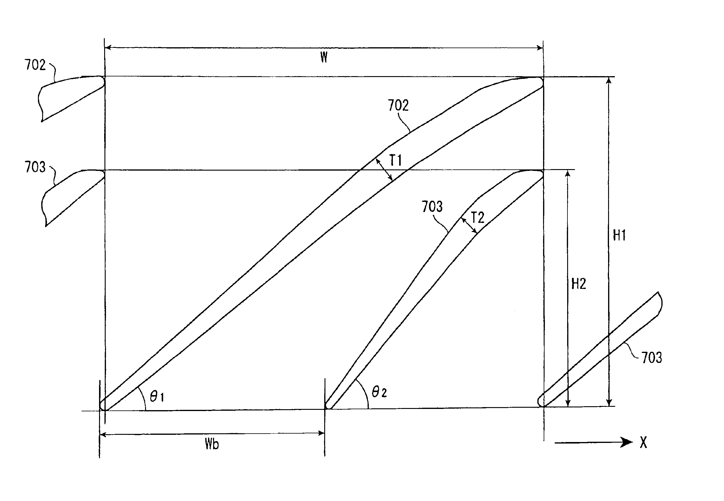
[0178]Further, the louver 721 in the first embodiment has the plurality of louver components 722 stretching from the center of the ...

experiment 1-1

[0216](Experiment 1-1)

[0217]The dimension of H2 was 6.8 mm (approximately half of H1).


PUM


Abstract

An axial-flow fan has a plurality of main fins (702), and auxiliary fins (703) provided between the main fins (702), where the position of a front end of the auxiliary fin (703) relative to X axis and the position of a front end of the main fin (702) adjoining the auxiliary fin in reverse-rotary direction are aligned, the height of the auxiliary fin (703) is approximately three fourths of the height of the main fin (702), and the cross sections of the main fin (702) and the auxiliary fin (703) taken along the axial direction of the main shaft are streamlined.

Description

BACKGROUND OF THE INVENTION[0001]1. Technical Field of the Invention[0002]The present invention relates to an axial-flow fan and a projector. More specifically, the present invention is directed to an axial-flow fan capable of securing high static pressure and reducing noise, which is suitably used for an apparatus having a light source, such as a projector.[0003]2. Description or Related Art[0004]Conventionally, a projector has been used for presentations at conferences, academic societies, exhibitions, etc. Such a projector modulates a light bean irradiated by a light source in accordance with image information to form an optical image, and projects the optical image in an enlarged manner.[0005]In such a projector, the luminance of the light source has to be enhanced for sharply displaying the optical image, and the heat generated by the light source has to be exhausted to the outside of the projector. Accordingly, a cooling mechanism is provided for drawing in external cooling ai...

Claims


Application Information

Patent Timeline
Patent Type & Authority Patents(United States)
IPC IPC(8): F04D29/38G03B21/16F04D29/32F04D29/54F04D29/66
CPCF04D29/327G03B21/16F04D29/666F04D29/542F04D29/703F04D29/544
Inventor FUJIMORI, MOTOYUKIKITAMURA, MASAKAZUHASHIZUME, TOSHIAKI
Owner SEIKO EPSON CORP
Why Eureka
Try Eureka