Switching device comprising a breaker mechanism

a technology of breaker mechanism and switch, which is applied in the direction of circuit-breaking switch, snap-action arrangement, dynamo-electric relay, etc., can solve the problems of unfavorable construction of this parameter, and achieve the effect of precise movement sequence, high guidance stability, and potential saving and simplification

Inactive Publication Date: 2006-03-07
SIEMENS AG
View PDF15 Cites 22 Cited by
  • Summary
  • Abstract
  • Description
  • Claims
  • Application Information

AI Technical Summary

Benefits of technology

[0013]The cutout is advantageously open or closed, thus providing a further potential saving and simplification in terms of the assembly of the device components, in particular the moveable contact arm.
[0014]The enclosure advantageously includes two enclosure shells, each having an accommodating element, the bolt being guided on both sides. This results in high guidance stability and a precise movement sequence.
[0015]The enclosure is preferably made of insulating material. In this case, the insulating properties of the insulating material are useful to the extent that they satisfy existing regulations on protection against electric shock. Further, in addition, they effect electrical and thermal decoupling between the device components and subassemblies.

Problems solved by technology

The circuit breaker of the prior art cited above does have, however, a construction which unfavorably influences this parameter.

Method used


Image

  • Switching device comprising a breaker mechanism
  • Switching device comprising a breaker mechanism
  • Switching device comprising a breaker mechanism

Examples


Embodiment Construction

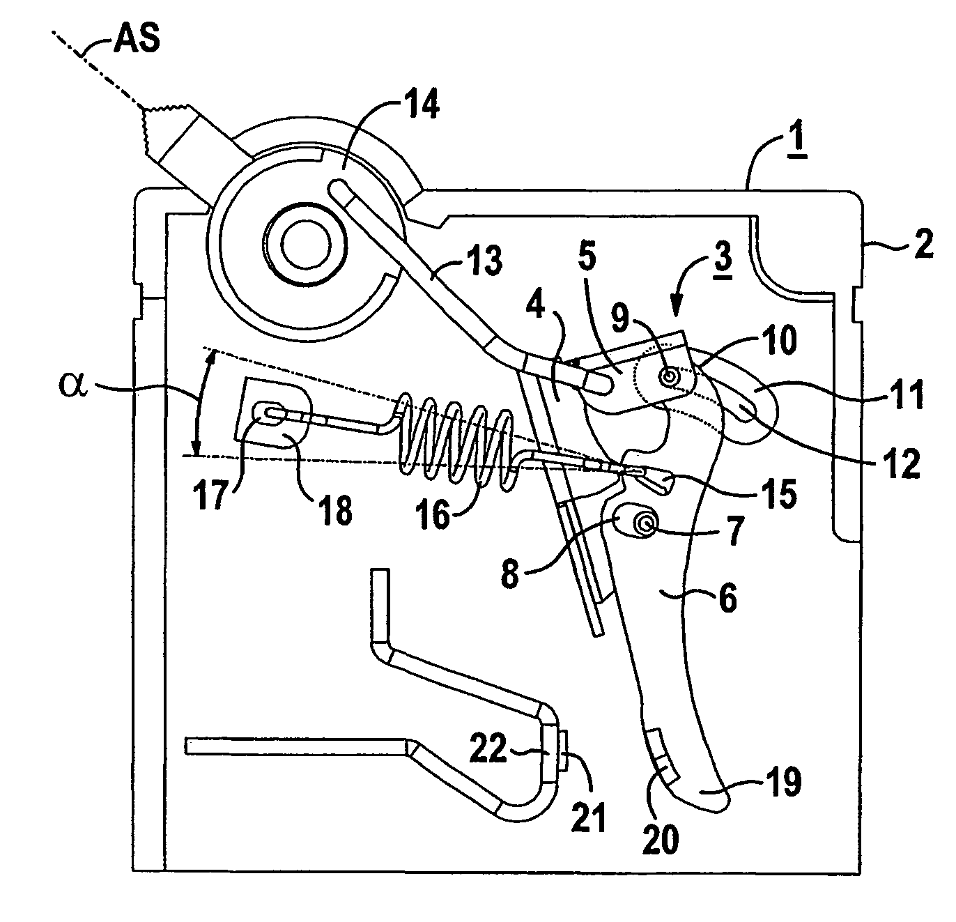
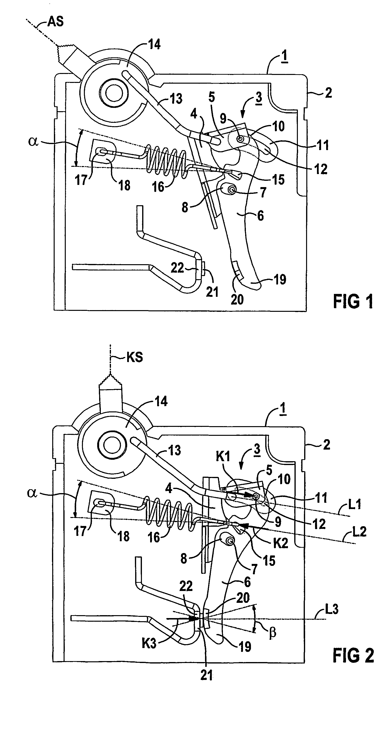
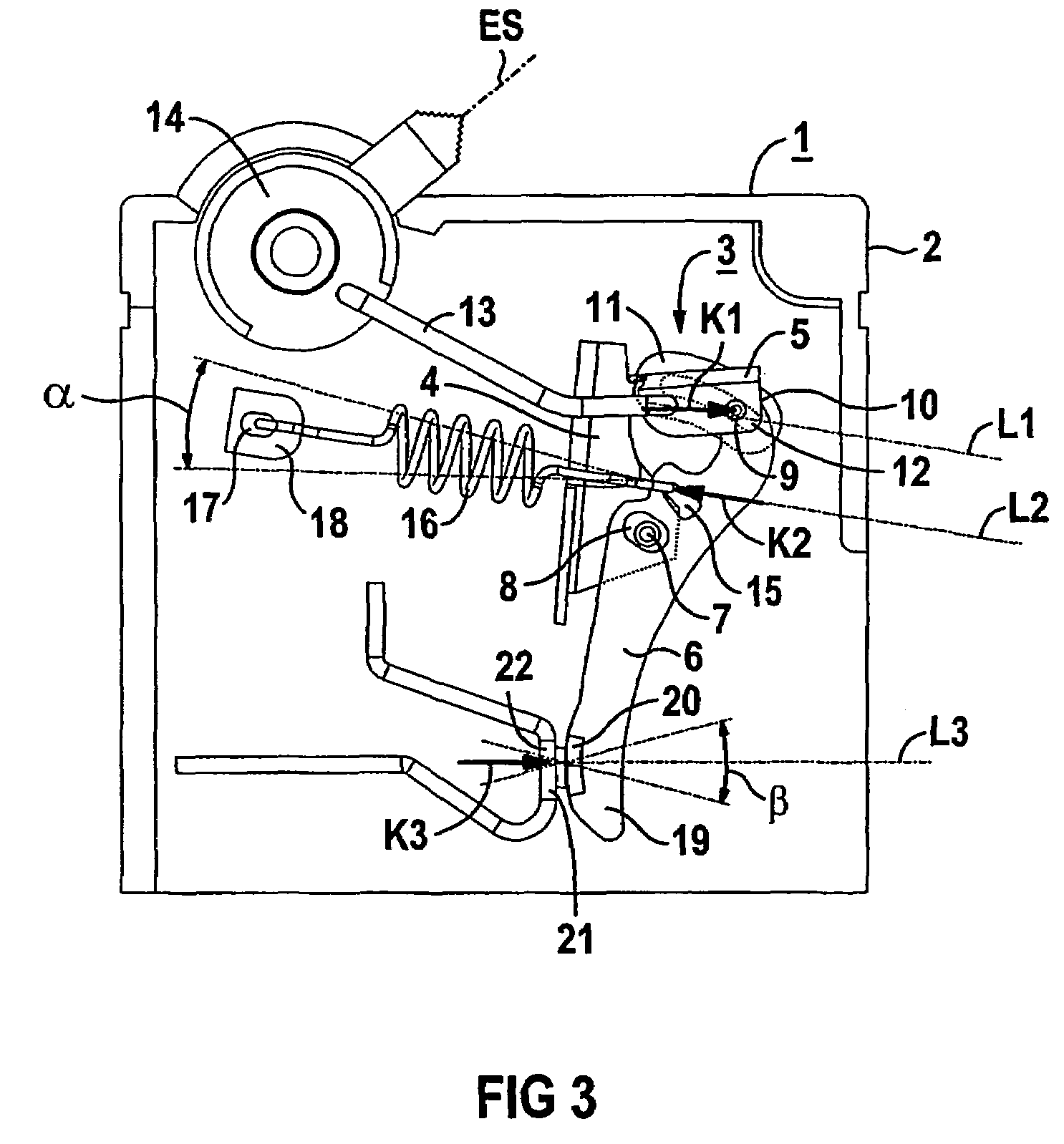
[0021]FIG. 1 shows a switching device 1 having an enclosure 2 and a latching or breaker mechanism 3 in the so-called off position AS. The latching mechanism 3 has a tripping lever 4, a latch 5, a moveable contact arm 6 and a deflection pin 7 fixed to the enclosure. The contact arm 6 has in this view an approximately mirror-reversed S shape and is provided approximately mid-way, in particular at a length ratio of 1:2, along its component length with a cutout 8, in which the deflection pin 7 is arranged.

[0022]The cutout 8 may be either open or closed and is directed essentially toward the tripping lever 4 with respect to the component width of the contact arm 6. The cutout 8 is larger than the deflection pin 7, which simplifies the assembly of the device components. The cutout 8, in conjunction with the deflection pin 7, serves only to hold the device components together. The deflection pin 7 is arranged largely freely in the cutout 8 and performs a limiting or deflecting function, po...


PUM


Abstract

A switching device including housing and a breaker mechanism, the latter consisting of a trip lever, a catch, a displaceable contact arm and a deflection shaft that is fixed to the housing. The aim is to generate a constant contact force. To achieve this, the end of the catch is coupled to the displaceable contact arm by way of a bolt. The bolt is configured to be displaced in a receiving element that is formed by the housing.

Description

[0001]This application is the national phase under 35 U.S.C. § 371 of PCT International Application No. PCT / DE02 / 02476 which has an International filing date of Jul. 5, 2002, which designated the United States of America and which claims priority on German Patent Application number DE 101 33 878.3 filed Jul. 12, 2001, the entire contents of which are hereby incorporated herein by reference.FIELD OF THE INVENTION[0002]The invention generally relates to a switching device.BACKGROUND OF THE INVENTION[0003]A switching device, in particular a protective switching device, having a latching mechanism is used, for example, as a circuit breaker. Circuit breakers—also referred to as automatic circuit breakers—are predominantly used today in place of fuses. Circuit breakers are overcurrent circuit breakers having a first and a second tripping device which act on a latching mechanism. An electromagnetic tripping device effects instantaneous tripping in the event of a short circuit. A thermal bi...

Claims


Application Information

Patent Timeline
Patent Type & Authority Patents(United States)
IPC IPC(8): H01H5/00H01H71/52
CPCH01H71/526H01H2071/0292
Inventor VIERLING, WINFRIED
Owner SIEMENS AG
Why Eureka
Try Eureka