Portable magnetic resonance surface coil unit with an access opening for manual gripping

Active Publication Date: 2006-03-07
SIEMENS HEALTHCARE GMBH
View PDF8 Cites 22 Cited by
  • Summary
  • Abstract
  • Description
  • Claims
  • Application Information

AI Technical Summary

Benefits of technology

[0009]An object of the present invention is to s

Problems solved by technology

As the examination region increases, MR surface coil units become ever larg

Method used


Image

  • Portable magnetic resonance surface coil unit with an access opening for manual gripping
  • Portable magnetic resonance surface coil unit with an access opening for manual gripping
  • Portable magnetic resonance surface coil unit with an access opening for manual gripping

Examples


Embodiment Construction

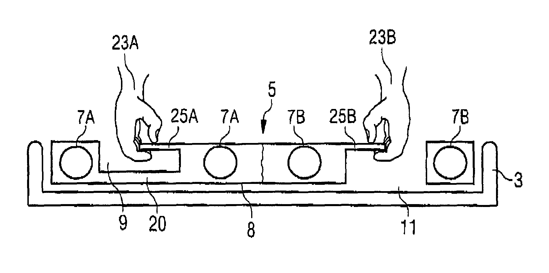
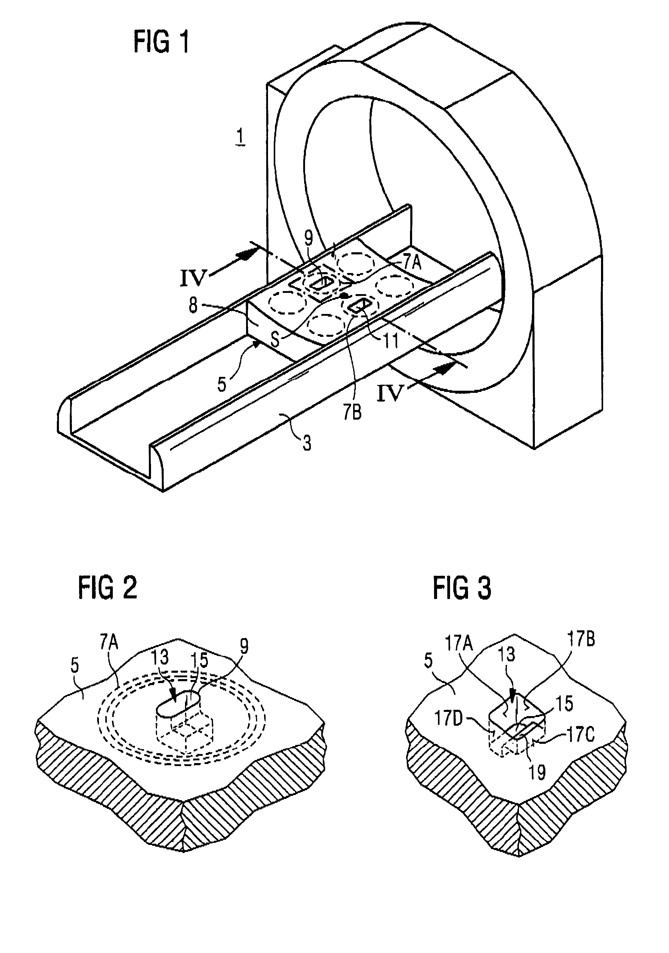
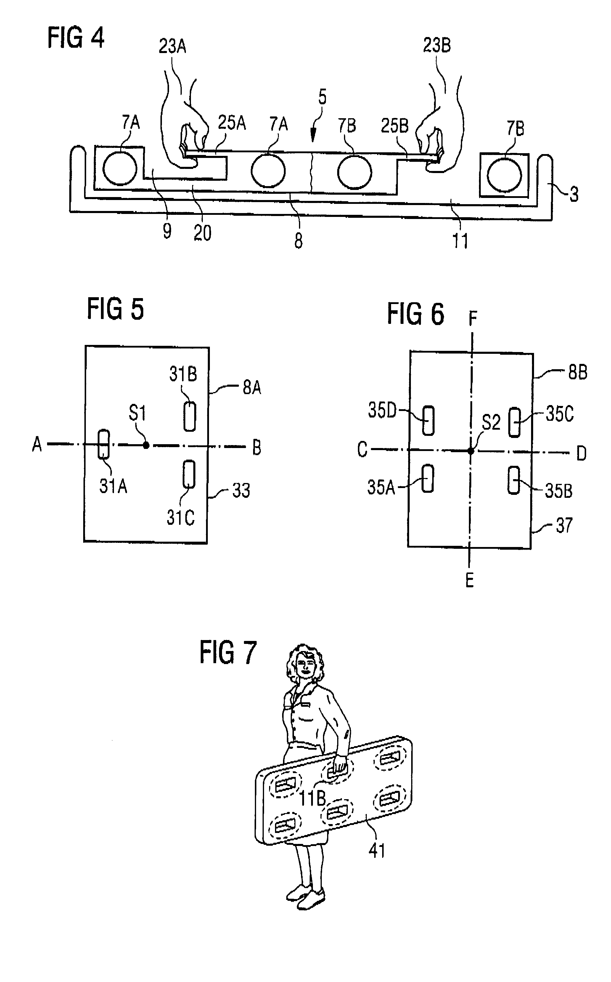
[0027]FIG. 1 shows an MR device 1 with a patient bed 3 on which a spinal column coil unit 5 is placed. The spinal column coil unit 5 is formed as a coil array that has a number of array coils 7A, 7B that provide an MR reception signal from which, for example, a spinal column exposure can be generated. The spinal column coil unit 5 has a length of approximately 1.20 m, a width of approximately 50 cm and a thickness of a few centimeters. It has an essentially closed housing 8 that is, for example, concave in the support region. At the edges, it fits flush to the patient bed 3 that is U-shaped. Two recessed grips 9, 11 are arranged on opposite sides of the spinal column coil unit 5 at the height of the center of gravity S. Each has an access opening to a cavity which is located in the region surrounded by one of the array coils 7A, 7B. If, for example, the spinal column coil unit 5 weighing approximately 12 kg is to be taken from the patient bed 3, the operating personnel can act with ...


PUM


Abstract

A magnetic resonance surface coil unit has at least one magnetic resonance coil surrounded by a closed housing wherein the housing has at least one recessed grip, and the recessed grip is formed by an oblong access opening to the cavity arranged inside of the housing. The cavity extends behind the access opening to one side in the direction of a shorter dimension of the access opening, such that a region of the housing bordering the access opening forms a grip part of the recessed grip. The recessed grip can be arranged in a region surrounded by a magnetic resonance coil.

Description

BACKGROUND OF THE INVENTION[0001]1. Field of the Invention[0002]The present invention concerns a magnetic resonance surface coil unit with at least one magnetic resonance resonator.[0003]2. Description of the Prior Art[0004]Examinations with a magnetic resonance device (MR device) today can extend over larger regions of the human body. The MR exposures necessary for this are mostly acquired with MR surface coil units. These completely cover the body section to be examined. As the examination region increases, MR surface coil units become ever larger, heavier and unwieldy.[0005]An example of such an MR surface coil is a spinal column coil, the length of which corresponds to the entire length (approximately 1.20 m) of the human spinal column and the width of which is for the most part given by the width of the patient support (approximately 0.50 m), i.e. the width of the human upper body. A weight of approximately 12 kg results based on this size. Handling of this spinal column coil i...

Claims


Application Information

Patent Timeline
IPC IPC(8): G01V3/00G01R33/341
CPCG01R33/341
Inventor HAHN, HEINZMATSCHL, VOLKER
Owner SIEMENS HEALTHCARE GMBH
Why Eureka
Try Eureka