PLL employing a sample-based capacitance multiplier

a capacitance multiplier and sample-based technology, applied in pulse generators, pulse techniques, instruments, etc., can solve problems such as clock signals, excessive jitter, and difficult analysis

Active Publication Date: 2006-03-07
AVAGO TECH INT SALES PTE LTD
View PDF3 Cites 22 Cited by
  • Summary
  • Abstract
  • Description
  • Claims
  • Application Information

AI Technical Summary

Problems solved by technology

PLLs with bang-bang PDs are only nearly “locked” to the input data and form non-linear systems that make analysis difficult.
However, bang-bang PDs may introduce excessive jitter in the resulting clock signal since the clock is shrunk or expanded at every edge transition.

Method used


Image

  • PLL employing a sample-based capacitance multiplier
  • PLL employing a sample-based capacitance multiplier
  • PLL employing a sample-based capacitance multiplier

Examples


Embodiment Construction

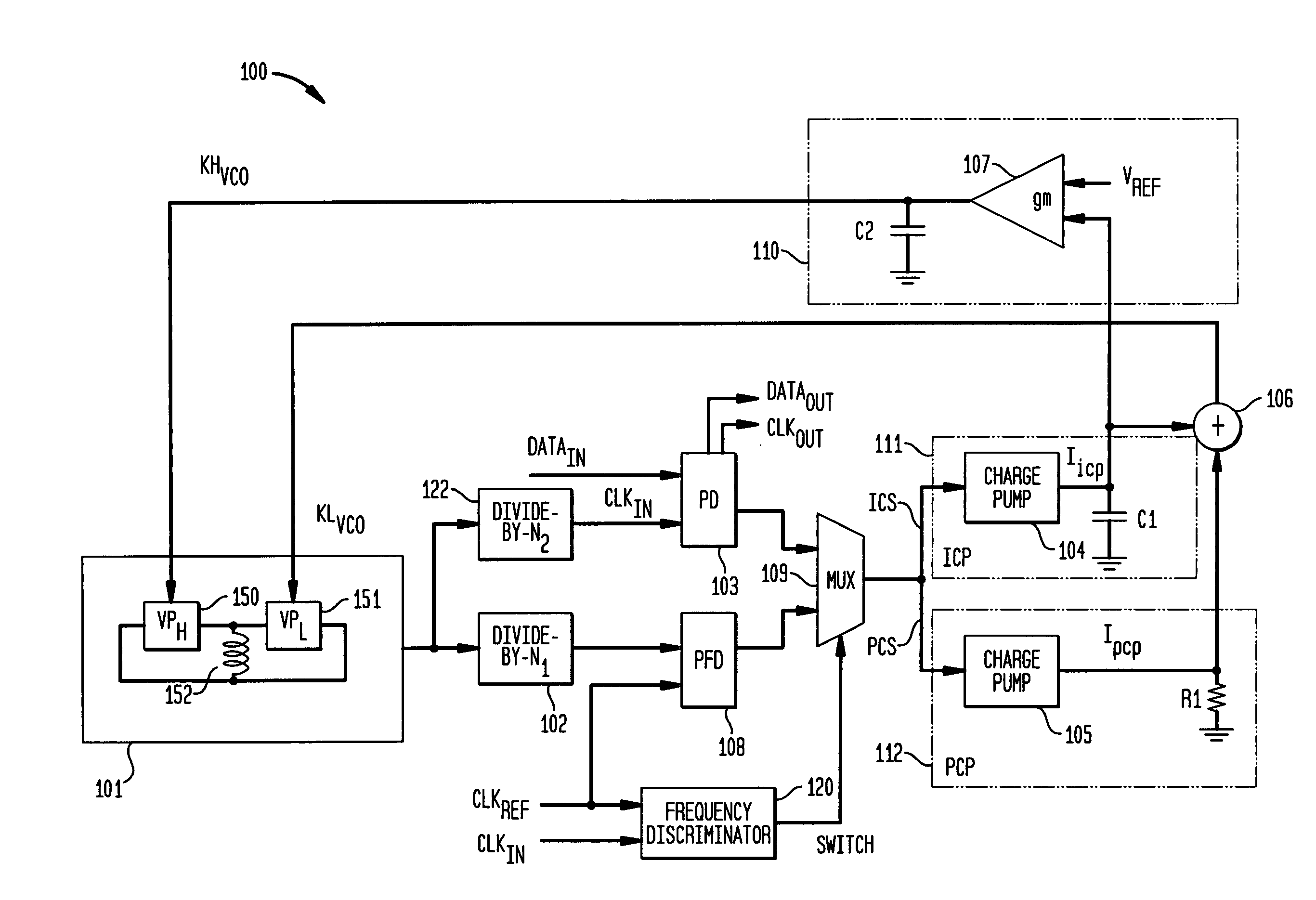
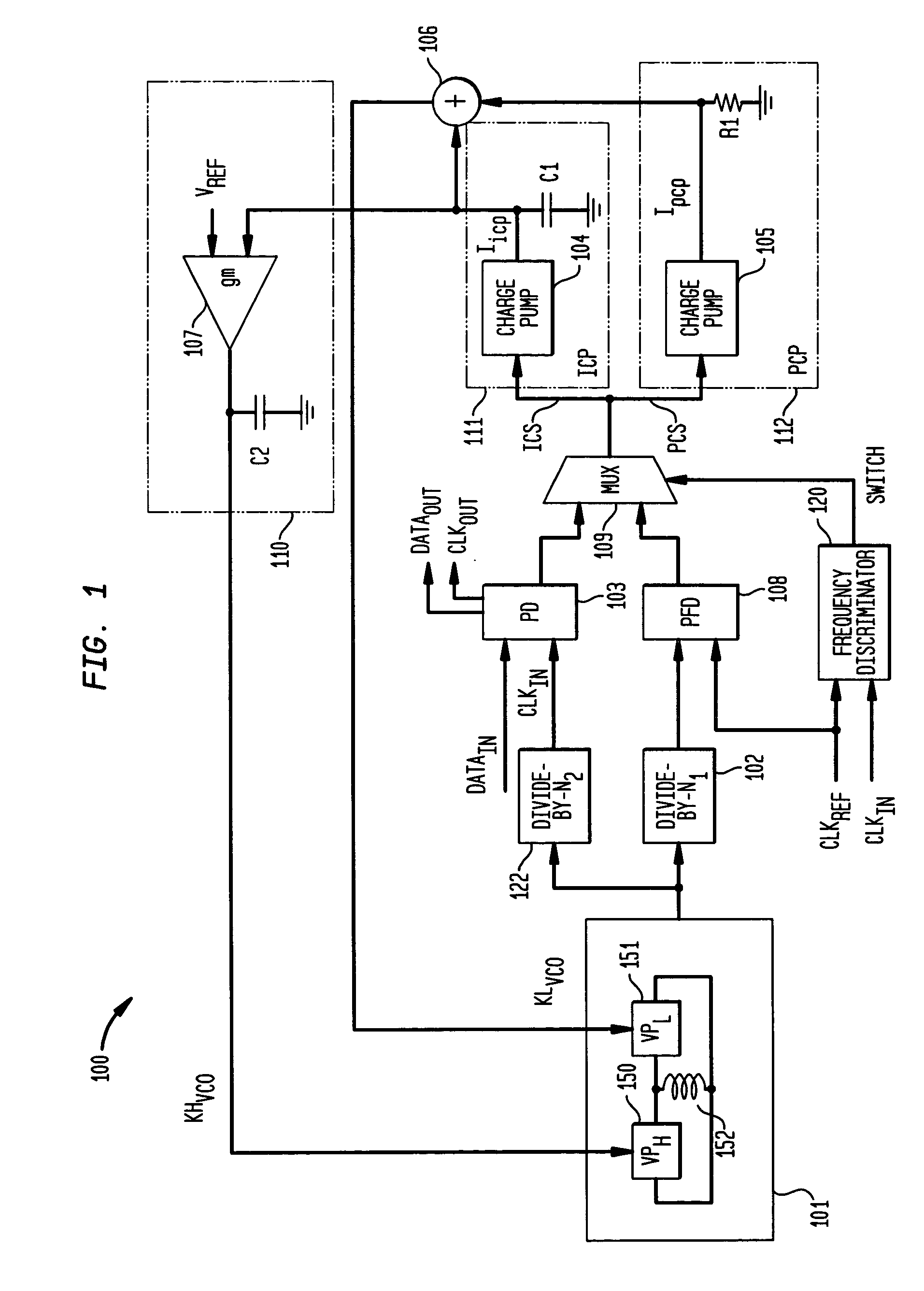
[0017]FIG. 1 shows a block diagram of phase-locked loop (PLL) 100 operating in accordance with an exemplary embodiment of the present invention. PLL 100 comprises voltage controlled oscillator (VCO) 101, divide-by-N1 102, divide-by-N2 122, phase detector (PD) 103, integral charge pump (ICP) 111 having charge pump 104 and capacitor C1, proportional charge pump (PCP) 112 having charge pump 105 and resistor R1, voltage adder 106, and process / voltage / temperature (PVT) compensator 110 including amplifier 107 and capacitor C2. Though not explicitly shown in FIG. 1, charge pumps 104 and 105 are coupled to a common ground and biased with a reference voltage Vref PLL 100 tends to synchronize the frequency of the signal provided by VCO 101 to a frequency that is a multiple of the frequency of the input data DATAin.

[0018]VCO 101 is desirably implemented as an inductor-capacitor (LC) oscillator having a fixed inductor value and a variable capacitor value. The variable capacitor value may be imp...


PUM


Abstract

A phase detector (PD) generates an up / down signal based on the phase error between data and clock signals input to the phase detector. A voltage controlled oscillator (VCO) generates the clock signal. The up / down signal is applied to a proportional charge pump and a truncated version of the up / down signal is applied to an integral charge pump. The proportional charge pump generates a first voltage for a first time period across a resistor based on the up / down signal, while the integral charge pump generates a second voltage for a second time period across a capacitor based upon the truncated version of the up / down signal and the sampling rate of the data signal by the PD. The second time period is less than the first time period. The first and second voltages are combined and applied to the VCO to drive the clock signal to synchronization with the data.

Description

BACKGROUND OF THE INVENTION[0001]1. Field of the Invention[0002]The present invention relates to phase-locked loop (PLL) circuits, and, more particularly, to charge-pump PLLs.[0003]2. Description of the Related Art[0004]A phase-locked loop (PLL) is a circuit that generates, or synthesizes, a periodic output signal that has a constant phase and frequency with respect to a periodic input signal. PLLs are widely used in many types of measurement, microprocessor, and communication applications. One type of phase-locked loop is the charge-pump PLL, which is described in Floyd M. Gardner, “Charge-Pump Phase-Lock Loops” IEEE Trans. Commun., vol. COM-28, pp. 1849–1858, November 1980, the teachings of which are incorporated herein by reference.[0005]In a conventional charge-pump phase-locked loop, a phase detector (PD) compares the phase θIN of the input signal to the phase θOUT of a feedback signal derived from the PLL output. Based on the comparison, the PD generates an error signal: eithe...

Claims


Application Information

Patent Timeline
Patent Type & Authority Patents(United States)
IPC IPC(8): H03L7/00H03L7/087H03L7/089H03L7/099H03L7/113H04L7/033
CPCH03L7/087H03L7/0893H04L7/033H03L7/113H03L7/099H03L2207/06
Inventor JASA, HRVOJEPOLHEMUS, GARY D.SCOGGINS, JOHN E.
Owner AVAGO TECH INT SALES PTE LTD
Why Eureka
Try Eureka