Gas dischargeable panel

a technology of gas discharge panel and electrode, which is applied in the direction of instruments, static indicating devices, and electrode addresses, etc., can solve the problems of increasing the need for achieving lower power consumption, increasing the need for achieving low power consumption, and difficult stable production, so as to reduce the capacitance of electrodes, increase the effect of power consumption and small area

Inactive Publication Date: 2006-03-07
PANASONIC CORP
View PDF19 Cites 28 Cited by
  • Summary
  • Abstract
  • Description
  • Claims
  • Application Information

AI Technical Summary

Benefits of technology

[0036]The present invention was conceived in view of the problem described above, and aims to provide a gas discharge panel that has favorable display performance with high luminance and illumination efficiency.
[0037]Also, the present invention aims to provide a gas discharge panel which uses a display electrode structure divided into a plurality of parts without an increase in drive voltage. Furthermore, the present invention aims to provide a gas discharge panel that defies disconnections of divided electrode parts, has low-resistance electrodes, and is easy to drive.
[0040]With this construction, each of the display electrodes 4 and 5 are made up of a plurality of line parts and at least one connector part. Such a display electrode has a smaller area than a conventional strip-shaped display electrode, with it being possible to decrease the electrode capacitance needed for discharge. In general, if a display electrode is simply made up of a plurality of separate line parts, discharge takes place in a discrete fashion. As a result, the discharge current waveform tends to have a plurality of peaks. This increases the discharge firing voltage, thereby causing an increase in power consumption. According to the present invention, on the other hand, the discharge current waveform has a single peak as explained above, and so the panel can be driven with a lower voltage. Therefore, the power consumption can be reduced when compared with the conventional panel. This benefits favorable illumination efficiency (drive efficiency).
[0041]Also, since the discharge current waveform has a single peak, a voltage drop which could affect the panel luminance or the illumination efficiency does not occur. Furthermore, stable discharge can be performed even if a rise time of a drive pulse becomes unstable. Thus, the gas discharge panel of the present invention can express a gray scale by pulse modulation with stability.
[0042]When the cell width differs for each of the colors of red, green, and blue, the discharge firing voltage differs too. This makes it difficult to produce a stable image display. This problem associated with different cell widths can be solved if the above display electrode structure is used. This further increases the effects of the present invention (i.e. high illumination efficiency and stable image display).

Problems solved by technology

Due to the recent increases in the size and resolution of PDPs, the power consumption for PDPs tends to increase.
This heightens the needs for technologies that achieve lower power consumption.
However, when such a structure is used, the following problem arises.
According to this method, however, the precision of bonding the front panel FP and the back panel BP together becomes strict around 10–20 μm, which makes stable production more difficult.
This causes a voltage drop, thereby making it difficult to drive the PDP.

Method used


Image

  • Gas dischargeable panel
  • Gas dischargeable panel
  • Gas dischargeable panel

Examples


first embodiment

(First Embodiment)

1-1. Structure of a Display Electrode

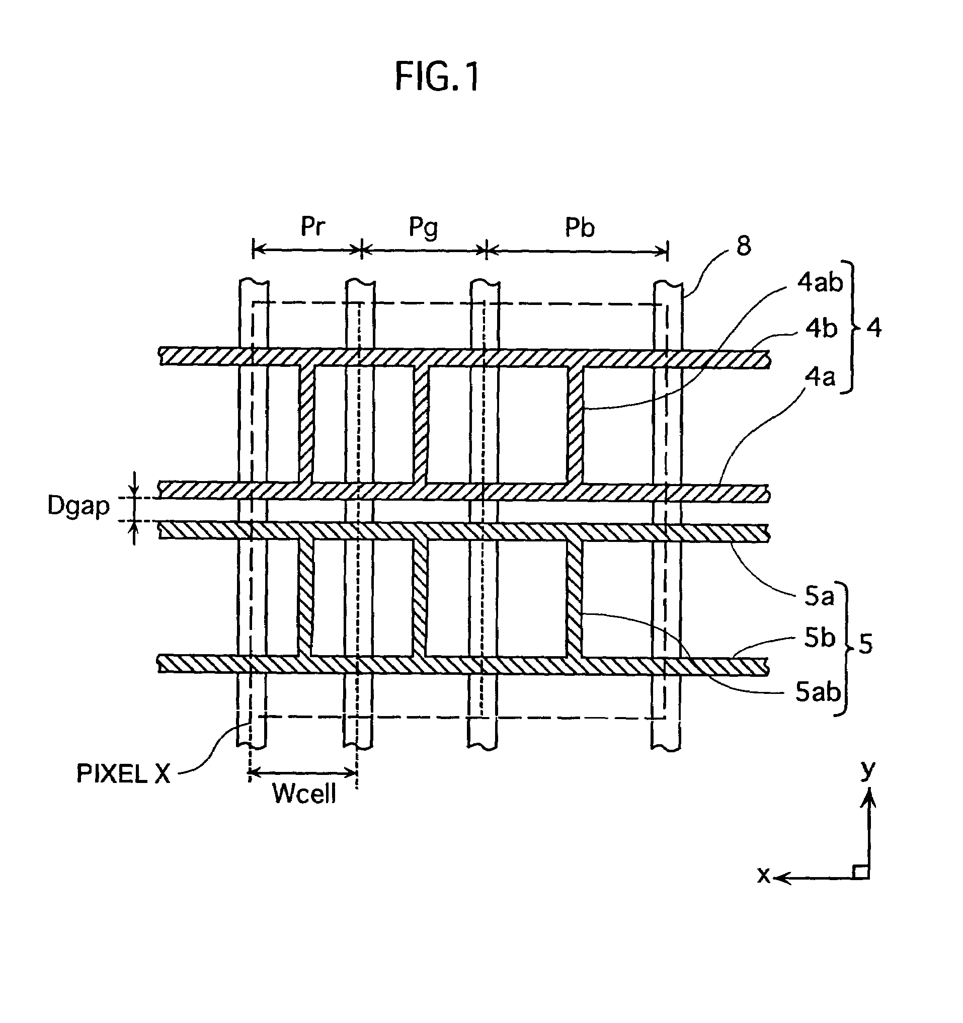
[0074]FIG. 1 is a plan view of a display electrode pattern which is the first embodiment of the present invention.

[0075]In this embodiment, the phosphor layers 9 are formed such that phosphor materials of the three primary colors are applied in the x direction in the order of, for example, red, green, and blue (RGB), so as to extend in the y direction. An area where one pair of display electrodes 4 and 5 intersect one address electrode 11 is a discharge cell. Three cells of red, green, and blue which are adjacent in the x direction constitute one pixel X, as shown in FIG. 1.

[0076]The panel of the first embodiment is characterized in that at least one of the scan electrode 4 and the sustain electrode 5 which form each pair is divided into three parts. A part that is closest to the other electrode of the pair is a line part 4a (5a). The distance between the line part 4a (5a) and the other electrode is a main discharge gap Dgap. Th...

second embodiment

(Second Embodiment)

2-1. Structure of a Display Electrode

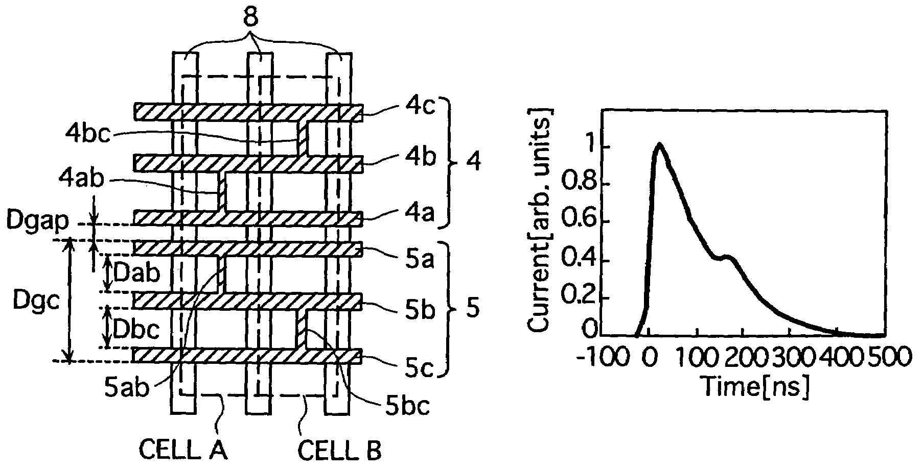
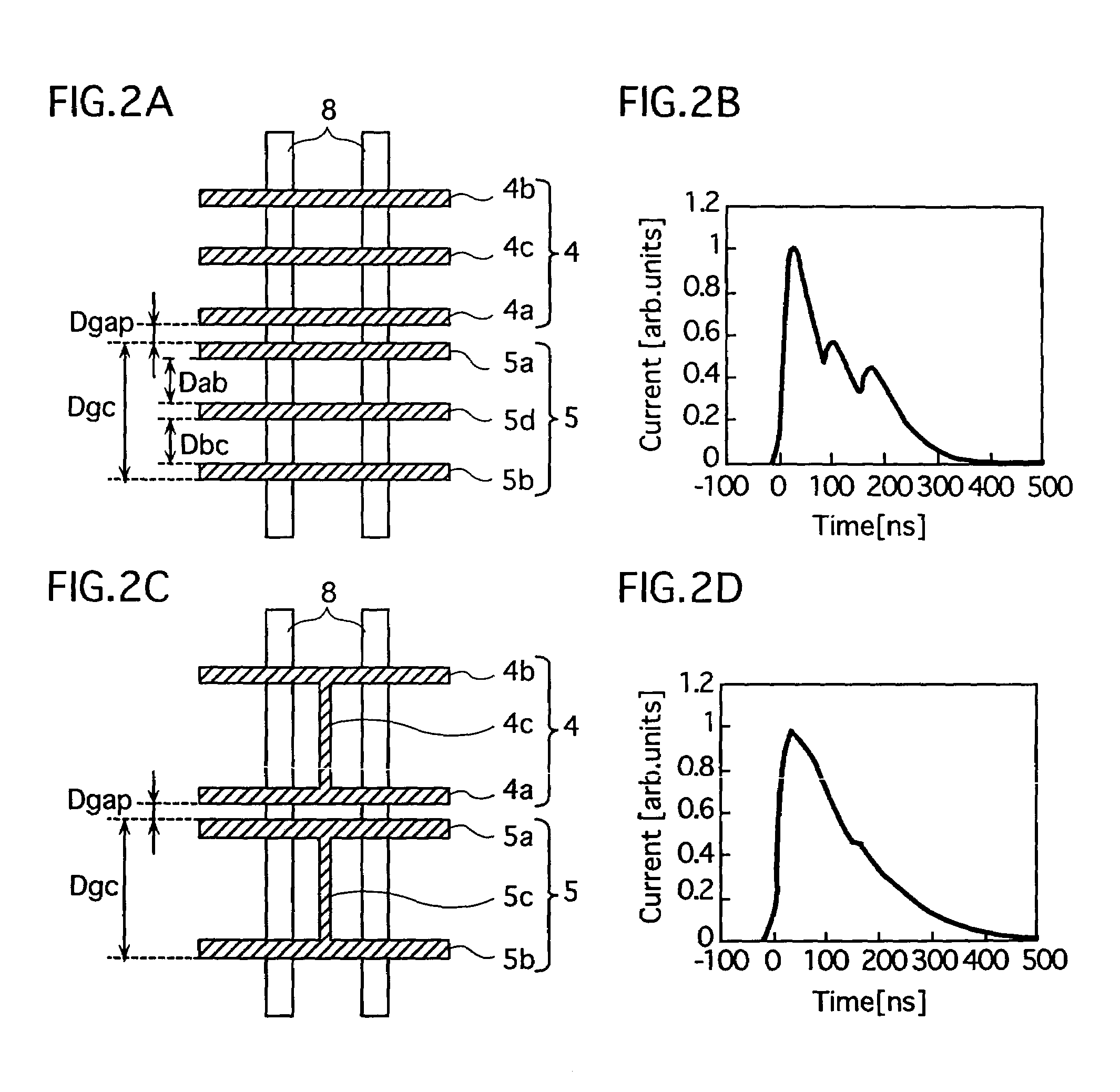
[0149]The second embodiment is fundamentally based on the first embodiment, but is characterized in that a display electrode is made up of three or more line parts 4a, 4b, . . . and connector parts 4ab, 4bc, . . . which are arranged in he y direction in a straight line to connect the line parts.

[0150]FIG. 10 shows an example of the display electrode structure of the second embodiment. In the drawing, the scan electrode 4 (sustain electrode 5) has three line parts 4a–4c (5a–5c) that are connected by connector parts 4ab and 4bc (5ab and 5bc) arranged in a straight line in the y direction. The distance Dab between the line parts 4a and 4b (5a and 5b) is equal to the distance Dbc between the line parts 4b and 4c (5b and 5c). It is preferable for Dab and Dbc to be larger than the main discharge gap Dgap, to increase the opening ratio. As a result, high luminance can be obtained, and the voltage can be further reduced.

[0151]As one ex...

third embodiment

(Third Embodiment)

3-1. Structure of a Display Electrode

[0189]In the first and second embodiments, a display electrode is made up of at least two line parts and at least one connector part which electrically connects the line parts, when the red cell, the green cell, and the blue cell have different widths in the x direction.

[0190]In the third embodiment, the display electrode 4 (5) includes three line parts 4a–4c (5a–5c) and projection parts 4aq and 4bq (5aq and 5bq) which are each provided on one side of any of the line parts 4a and 4b (5a and 5b) as a discharge developing part, as shown in FIG. 17. Here, the projection parts 4aq and 4bq (5aq and 5bq) have a rectangular shape, and are formed so as to extend in the y direction.

[0191]These projection parts 4aq and 4ba (5aq and 5bq) are formed such that the gap between adjacent line parts (e.g. 4a and 4b (5a and 5b)) is smaller in the areas corresponding to the channels between adjacent barrier ribs 8 than in the areas corresponding t...


PUM


Abstract

A gas discharge panel includes a first substrate and a second substrate. A plurality of display electrode pairs which are each made up of a sustain electrode and a scan electrode are formed on the first substrate, and the first substrate and the second substrate are set facing each other with a plurality of barrier ribs in between so as to form a plurality of cells. In this gas discharge panel, at least one of the sustain electrode and the scan electrode includes: a plurality of line parts; and a discharge developing part which makes a gap between adjacent line parts smaller in areas corresponding to channels between adjacent barrier ribs than in areas corresponding to the barrier ribs.

Description

[0001]This application is a 371 of PCT / JP01 / 07049, filed Aug. 16, 2001.[0002]1. Technical Field[0003]The present invention relates to a gas discharge panel such as a plasma display panel.[0004]2. Background Art[0005]Plasma display panels (PDPs) are one type of gas discharge panel. PDPs enable large-screen slimline televisions to be produced relatively easily, and so are receiving attention as next-generation display panels. Currently, sixty-inch models have already been commercialized.[0006]FIG. 26 is a partial sectional perspective view showing a main construction of a typical surface discharge AC (alternating current) PDP. In the drawing, the z direction is a direction along the thickness of the PDP, whilst the xy plane is a plane that is in parallel with the panel plane of the PDP. As illustrated, this PDP 1 is roughly made up of a front panel FP and a back panel BP which are set with their main surfaces facing each other.[0007]A front panel glass 2 serves as a substrate for the ...

Claims


Application Information

Patent Timeline
Patent Type & Authority Patents(United States)
IPC IPC(8): G09G3/28G09G3/20G09G3/291H01J11/12H01J11/22H01J11/24H01J11/26H01J11/32H01J11/34H01J17/49
CPCH01J11/12H01J11/32H01J11/24G09G3/2022G09G3/28H01J2211/323H01J2211/245G09G3/2927G09G2300/0426G09G3/291
Inventor NISHIMURA, MASAKIHIGASHINO, HIDETAKAMURAI, RYUICHITAKADA, YUUSUKENAGAO, NOBUAKIANDO, TORUKOSUGI, NAOKITACHIBANA, HIROYUKI
Owner PANASONIC CORP
Why Eureka
Try Eureka