Chiral boardband tuning apparatus and method

a technology of chiral boardband and tuning apparatus, which is applied in the direction of instruments, cladded optical fibres, optical elements, etc., can solve the problems of light sources, leds that do not provide the performance needed for certain applications, and their manufacture requires sophisticated and expensive microfabrication

a technology of chiral boardband and tuning apparatus, which is applied in the direction of instruments, cladded optical fibres, optical elements, etc., can solve the problems of light sources, leds that do not provide the performance needed for certain applications, and their manufacture requires sophisticated and expensive microfabrication

US7009679B2Active Publication Date: 2006-03-07CHIRAL PHOTOINICS

Image

  • Chiral boardband tuning apparatus and method
  • Chiral boardband tuning apparatus and method
  • Chiral boardband tuning apparatus and method

Examples


Embodiment Construction

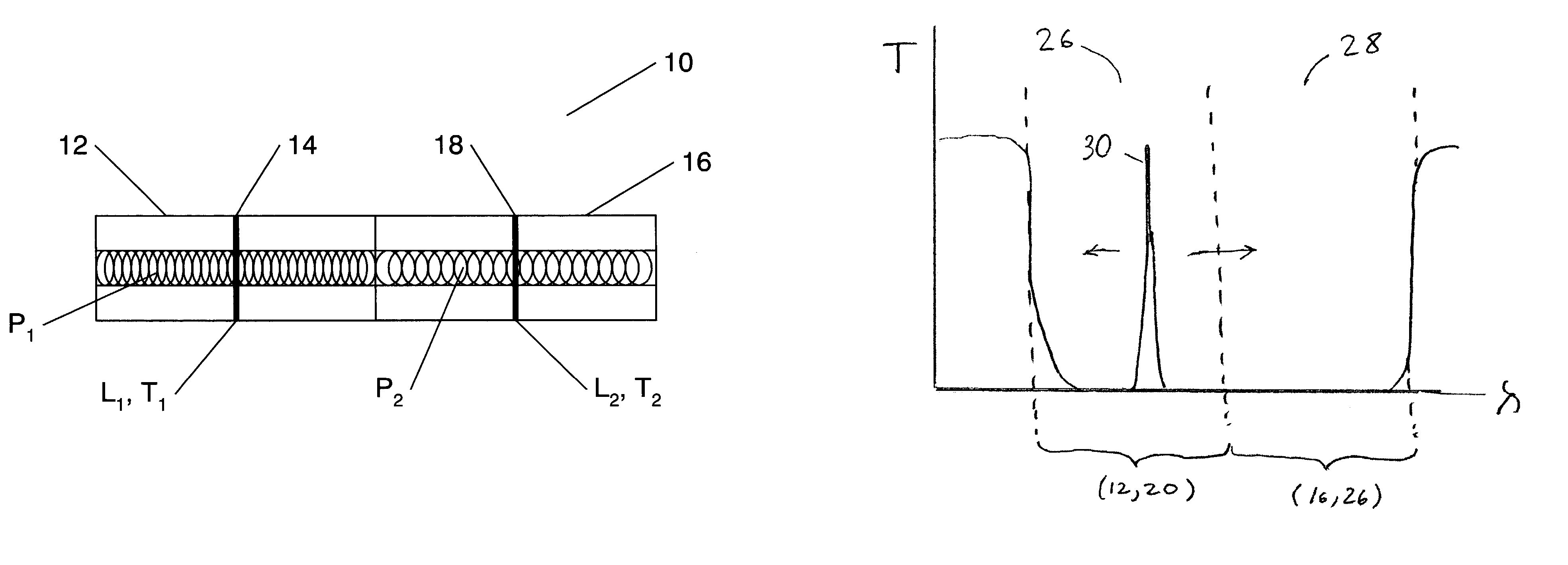
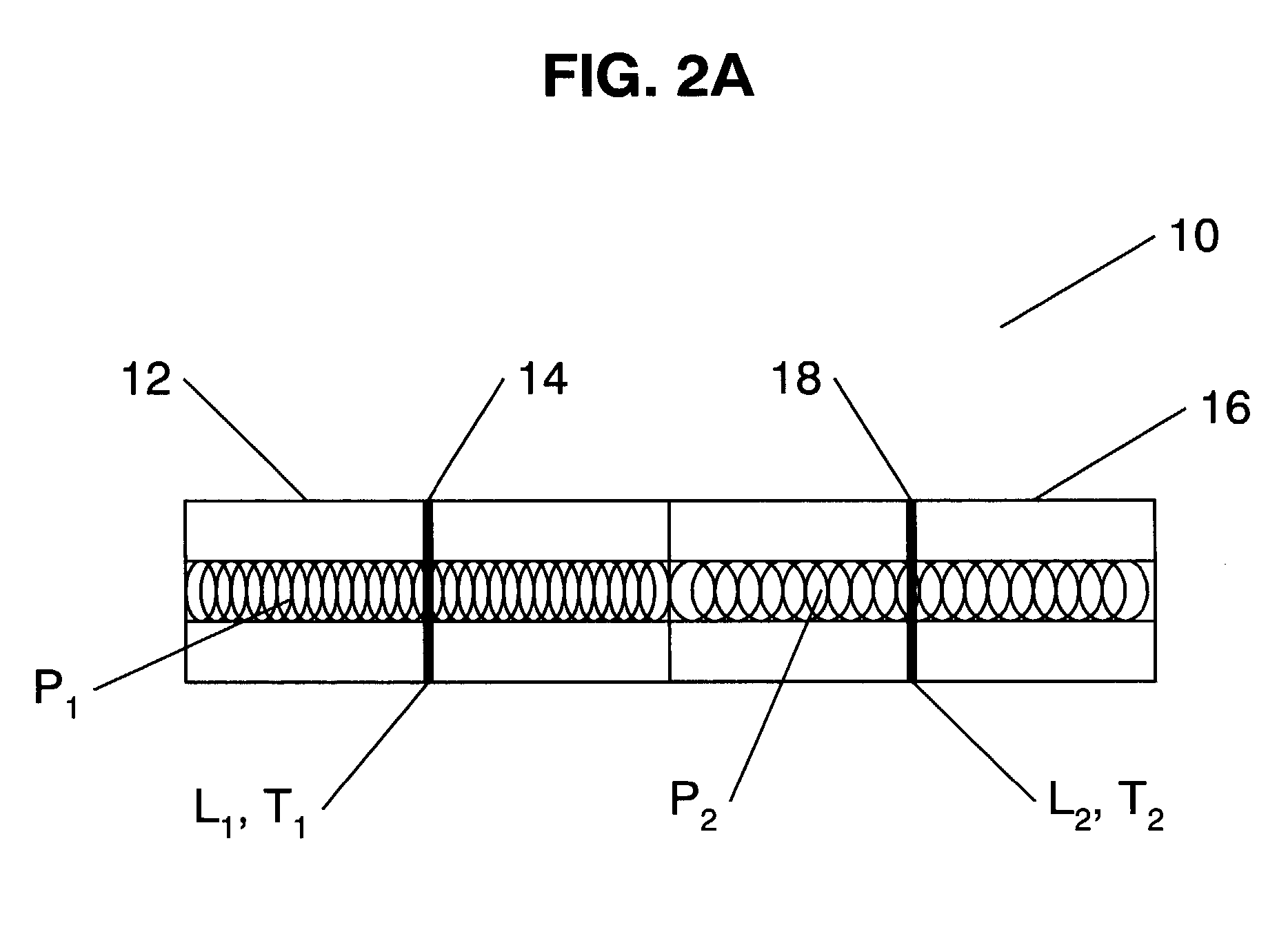
[0028]The present invention is directed to an advantageous broadband tunable chiral structure that provides broadband tunability through an expanded photonic band gap. The novel chiral structure can be implemented in a thin film chiral medium, or preferably, in a chiral optical fiber. The novel broadband thin film or fiber chiral structure can be readily tuned, utilizing a tunable chiral defect generator, by moving a defect state within the expanded photonic band gap (hereinafter “PBG”).

[0029]Before describing the present invention in greater detail, it would be helpful to provide definitions of common terms utilized in the dielectric component. “Chiral” materials are not symmetrical on a molecular level—that is molecules of chiral materials are not identical to their mirror images. Cholesteric materials, such as cholesteric liquid crystals (hereinafter “CLCs”), have multiple molecular layers in which molecules in the different layers are oriented on average at a slight angle relati...


PUM


Abstract

A chiral structure having an expanded adjustable reflection band to provide broadband tunability is provided. In the preferred embodiment, the chiral structure is implemented as a chiral fiber structure and comprises two or more sequential chiral fiber elements of different pitches, each having a tunable chiral defect generator. The pitches are selected such that the individual photonic band gaps of the elements are formed into one expanded reflection band such that at least one defect state can be formed and moved within the expanded reflection band by selectively activating and adjusting one or more of the tunable chiral defect generator. The tunable chiral defect generators may generate and control defect state(s) in the structure's spectral response by introducing chiral twists and / or spacing between the chiral elements, with the length of the spacings and angles of chiral twists being proportional to the position of the defect state(s) within the reflection band of the structure.

Description

CROSS REFERENCE TO RELATED APPLICATIONS[0001]The present patent application claims priority from the commonly assigned U.S. provisional patent application Ser. No. 60 / 364,954 entitled “Chiral Fiber Structure with Broadband Tuning Capability” filed Mar. 14, 2002.FIELD OF THE INVENTION[0002]The present invention relates generally to fiber gratings and functionally equivalent structures, and more particularly to fiber gratings having an expanded adjustable reflection band that are implemented in a chiral structure to provide broadband tunability.BACKGROUND OF THE INVENTION[0003]Semiconductor lasers have found many industrial and commercial applications in recent years. For example, lasers are used in telecommunications, in pickups for optically readable media used in CD players, CD ROM drives and DVD players, in medical imaging, and in video displays. However, previously known semiconductor lasers have a number of disadvantages. For example, traditional semiconductor lasers, such as on...

Claims


Application Information

Patent Timeline
07 Mar 2006
Publication
US7009679B2
IPC
G02F1/13; H01S3/08; G02B6/02; G02B6/12; G02B6/122; G02B6/34
CPC
B82Y20/00; G02B6/0208; G02B6/12007; G02B6/1225; G02B6/02085; G02B2006/0209
Inventors
KOPP, VICTOR IL'ICH; GENACK, AZRIEL ZELIG