Multifunctional optical assembly

Inactive Publication Date: 2006-03-07
3M INNOVATIVE PROPERTIES CO
View PDF27 Cites 104 Cited by
  • Summary
  • Abstract
  • Description
  • Claims
  • Application Information

AI Technical Summary

Benefits of technology

[0009]The voids between the light management component and the light delivery component may provide advantages when the light management component is constructed in a manner such that its functioning is improved when, e.g., an air interface, can be maintained over substantial portions of the entry surface. Although the voids may often be occupied by air, it will be understood that any other gas or gases that provide a desirable index of refraction differential with the entry surface may occupy the voids. For example, the voids may be occupied by one or more gases

Problems solved by technology

This approach can, however, increase the cost of assembling the optical display because of the need to assemble the prismatic structured surface film with the other components in the optical display system.
The layering approach may also lead to inconsistencies in appearance of the optical display as the air gap betwee

Method used


Image

  • Multifunctional optical assembly
  • Multifunctional optical assembly
  • Multifunctional optical assembly

Examples


Example

[0023]In the following detailed description of the embodiments, reference is made to the accompanying drawings which form a part hereof, and in which are shown, by way of illustration, specific embodiments in which the invention may be practiced. It is to be understood that other embodiments may be utilized and structural changes may be made without departing from the scope of the present invention.

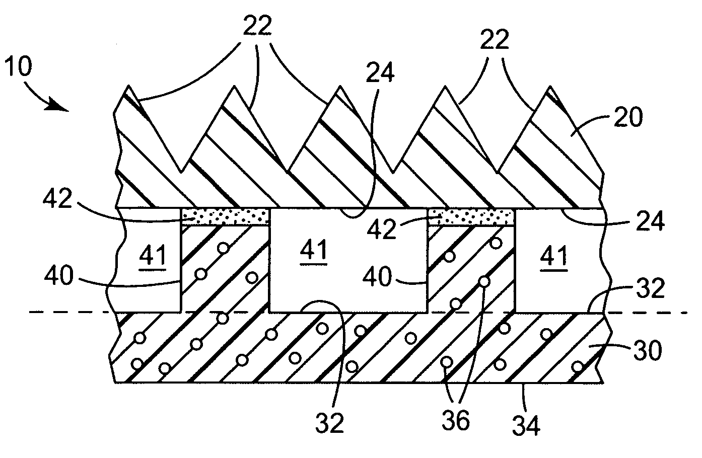
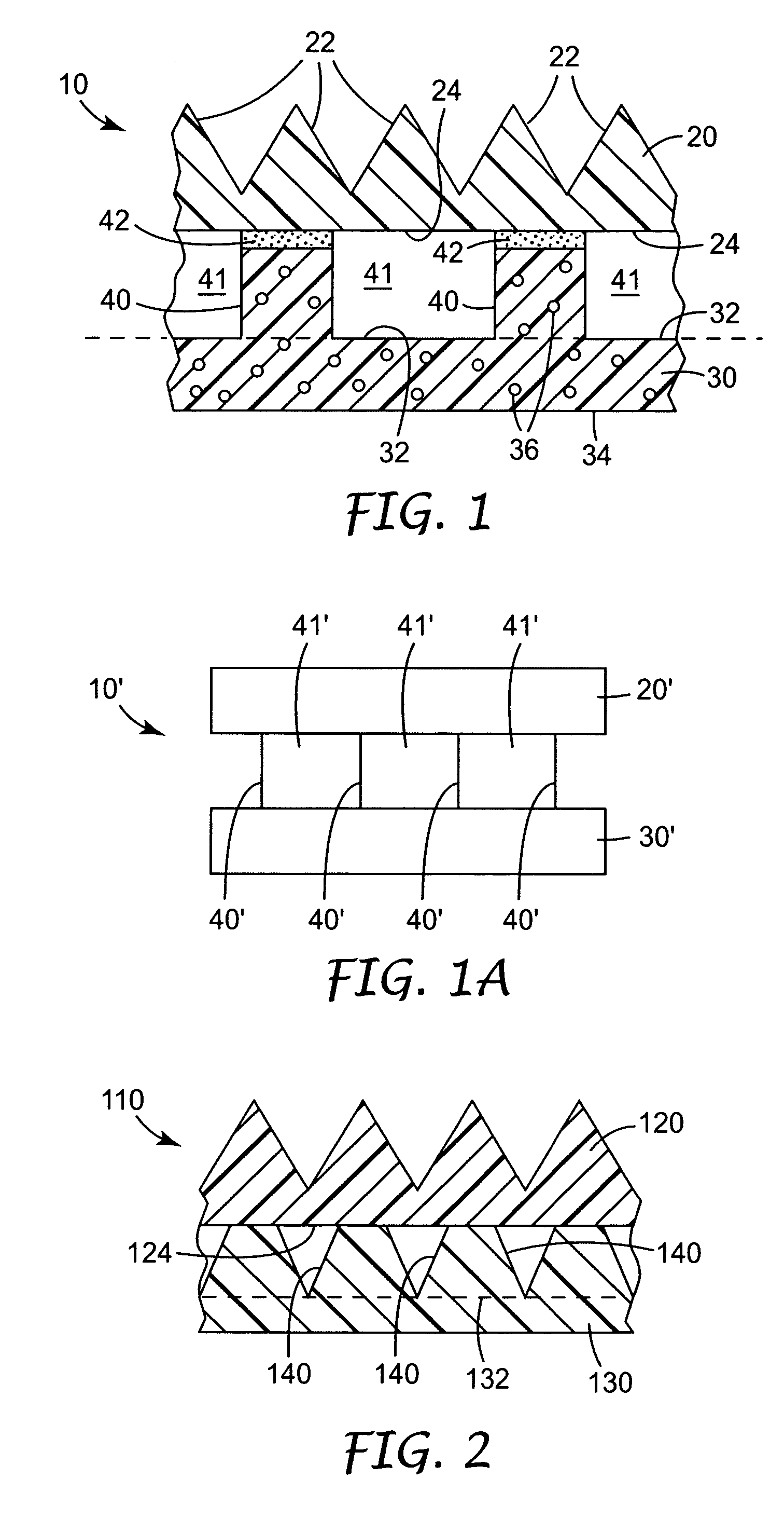
[0024]In some embodiments, the present invention as depicted in FIG. 1A provides an optical assembly 10′ that includes a light management component 20′ integrated with a light delivery component 30′. The attachment between the two components 20′ and 30′ is such that voids 41′ are created between them and between attachment points 40′ at which the light management component 20′ and the light delivery component 30′ are attached.

[0025]The voids 41′ are unfilled voids, i.e., they typically include one or more gases such as, e.g., air, nitrogen, etc. The unfilled voids 41′ preferably have an i...


PUM


Abstract

An integrated optical assembly including a light management component with an entry surface and a light delivery component having an exit surface attached to the entry surface of the light management component is disclosed The light management component and the light delivery component are attached together in a manner that defines voids between the entry surface of the light management component and the exit surface of the light delivery component. The voids between the light management component and the light delivery component may provide an air interface over substantial portions of the entry surface of the light management component.

Description

FIELD OF THE INVENTION[0001]The present invention relates generally to an optical assembly. More particularly, the invention relates to a multifunctional optical assembly for use in a display system.BACKGROUND[0002]A typical optical display system contains a light source that is required to observe the information presented by the display. In battery powered equipment like laptop computers, the light source can represent a substantial fraction of the total power draw of the equipment. Therefore, reducing the amount of power required to produce a given luminance can increase battery life, which may be especially desirable in battery powered equipment.[0003]The 3M brand Brightness Enhancement Film (BEF) available from the 3M Company of St. Paul, Minn., is one type of optical film that can be used to address this problem. BEF and similar films typically include an array of prisms on one surface that are large in comparison with the wavelengths of light. The structures can increase on-a...

Claims


Application Information

Patent Timeline
IPC IPC(8): G02B6/10G02B6/00G02B5/02G02B5/04G02B7/00G02F1/1335G02F1/13357
CPCG02B5/045G02B6/0025Y10S385/901G02B5/04G02B6/00
Inventor EMMONS, ROBERT M.LAMB, DAVID J.LIU, YAOQI J.LU, YING-YUHMEIXNER, LARRY A.MOSHREFZADEH, ROBERT S.POKORNY, RICHARD J.RHYNER, STEVEN J.WATSON, PHILIP E.WHITNEY, LELAND R.YANG, JIE
Owner 3M INNOVATIVE PROPERTIES CO
Why Eureka
Try Eureka