
Restocking system using a carousel

a carousel and restocking technology, applied in the field of carousel products, can solve the problems of increasing the cost, waste of unused supplies, long time spent driving rows, etc., and achieves the effect of minimizing the time between picks and the time spent driving rows

Inactive Publication Date: 2006-03-07
OMNICELL
View PDF107 Cites 150 Cited by
  • Summary
  • Abstract
  • Description
  • Claims
  • Application Information

AI Technical Summary

Benefits of technology

The carousel system enhances inventory management by reducing stock-outs, minimizing labor and time spent on restocking, and ensuring accurate inventory levels, thereby improving patient care and reducing operational costs while maintaining efficient supply chain operations.

Problems solved by technology

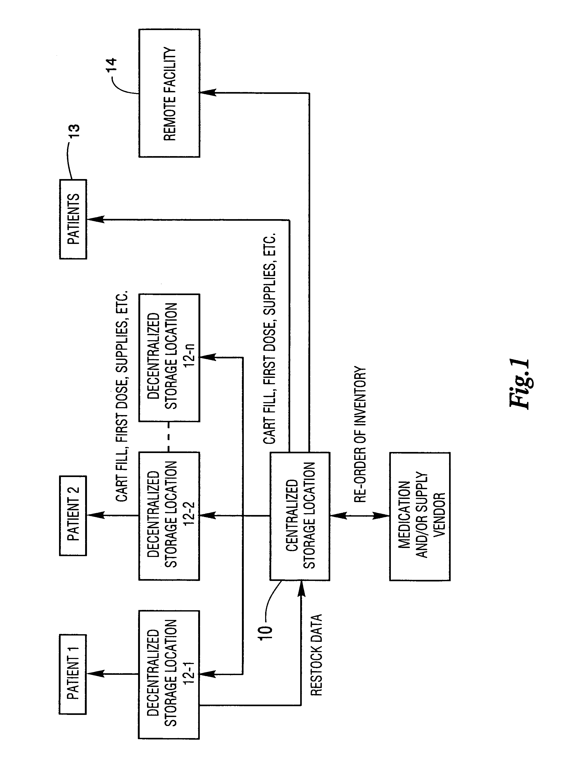
The departments utilizing medications and medical supplies in such facilities have long been burdened with the increasingly complex record keeping and inventory management that results from caring for hundreds, if not thousands, of patients every day.
It is also necessary to ensure that sufficient supplies are maintained at the decentralized and centralized storage locations without overstocking, because overstocking increases the cost of inventory by requiring more items to be maintained in inventory than are actually needed.
Overstocking of inventory can also result in waste through spoilage of unused supplies.
Excessive restocking of locations is also demanding on the facility's staff who must devote more of their time to monitor the storage locations to ensure that sufficient supplies are available.
Although these systems are generally effective in restocking locations, they suffer from a number of drawbacks.
One particular drawback is the potential for stock-outs that can arise if the inventories of the carts are not closely monitored.
Adequate inventory monitoring can be problematic due to time limitations on the staff.
Depletion of certain items from the carts can pose serious risks to the patients in the medical facility.
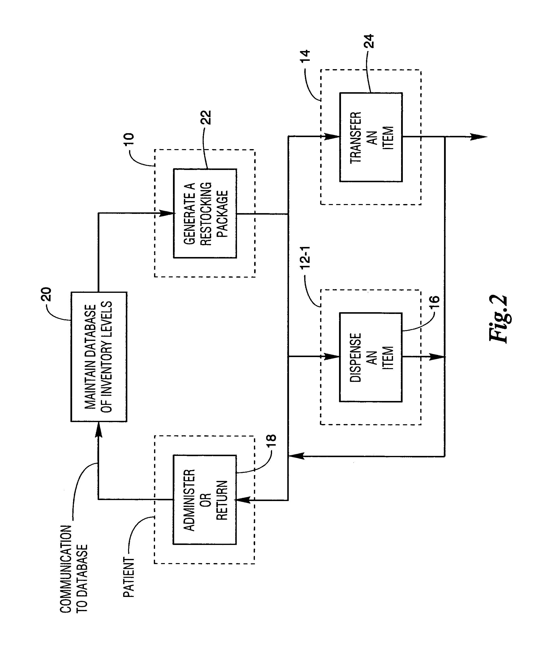
Another drawback is that restocking storage locations is a very labor-intensive and inefficient process, especially when accurate inventory levels are not maintained in the centralized or decentralized location.
The computers commonly provide for limited access by selected medical personnel to such carts and cabinets and limited access to specific drawers or locations therein in response to entry of information into the computer.
While the system of U.S. application Ser. No. 09 / 480,819 offers substantial advantages over other systems, some facilities may not have the resources to convert to such an automated system.
Further, the facility may have the need to restock items which cannot be easily placed into a restocking package by automated equipment because of their size, weight, or configuration.
Still other items may come from their manufacturers in bulk quantities or other types of packaging that make it difficult to automatically load them into a restocking package.

Method used


Image

  • Restocking system using a carousel
  • Restocking system using a carousel
  • Restocking system using a carousel

Examples


first embodiment

[0095]In the patient specific / room specific process:[0096]The picked medications are delivered into patient specific containers (envelope or bin) and may or may not be arranged in a time specific order.[0097]The container is loaded onto a mobile cart which is identified for a particular decentralized storage location (statically or dynamically). The mobile cart includes an on-board chip that carries the cart's ID. Information about the medications currently stocked in the cart is also maintained by the on-board chip.[0098]The cart is delivered to the decentralized location.[0099]The cart is electronically connected to the control computer 32 (FIG. 3). Once connected, the control computer recognizes the mobile cart's ID.[0100]Items are dispensed from the cart under the control of control computer 32. The mobile cart may include a visual indication to aid in the placement or retrieval of items.[0101]As items are dispensed from the mobile cart, information maintained by the on-board ch...

second embodiment

[0105]In the patient specific / room specific process:[0106]Picked medications are delivered into patient specific containers (envelope) and may or may not be arranged in a time specific order.[0107]The envelopes are loaded into a tote, see FIG. 11, which may include an on-board chip.[0108]The tote is delivered to a decentralized location (with a tower) and identified at the control computer 32.[0109]The tote is inserted into the tower or cabinet.[0110]Items are dispensed from the tower under the control of the control computer 32.[0111]Bar coded envelope and / or medications may be scanned at the decentralized storage location for verification.

third embodiment

[0112]In the patient specific / room specific process:[0113]Picked items are delivered into a patient specific container, and may or may not be arranged in a time specific order.[0114]Specific locations within the cabinet or auxiliary cabinet are designated as “patient specific pockets” and are lock-lidded.[0115]The user scans the container at the decentralized storage location.[0116]The control computer 32 recognizes the patient specific items and identifies the pocket into which the items are to be loaded.[0117]Items are then dispensed from the cabinet or auxiliary cabinet under the control of computer 32.[0118]Bar coded envelope and / or medications may be scanned at the decentralized storage location for verification.


PUM


Abstract

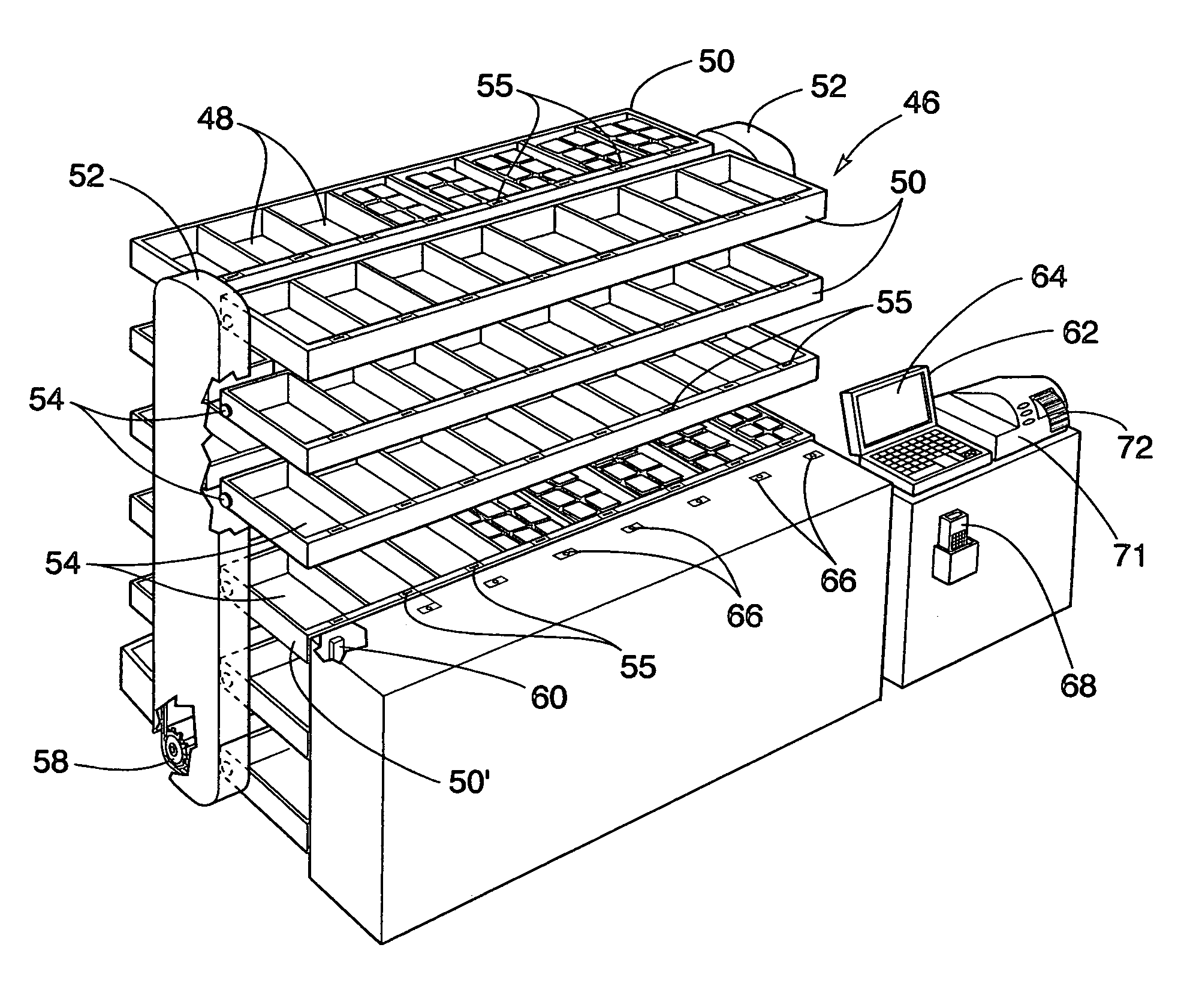
A carousel used in a restocking system is comprised of a drive track. A plurality of bins are arranged into rows, with the rows being driven by said drive track. A drive mechanism, e.g. an electric motor, drives the drive track. A sensor is provided to sense the position of the rows of bins. A processor is responsive to the sensor and data representative of a plurality of picks for more than one order for controlling the drive mechanism. By combining picks from different orders into a batch, the time spent driving the rows and time between picks is minimized. The carousel may be divided into a plurality of columns, each with its own drive track, drive mechanism, and sensor, to enable several rows to be brought into a pick position simultaneously. Various methods and forms of restocking packages are also disclosed.

Description

[0001]This application is a divisional of U.S. application Ser. No. 09 / 998,488 filed Nov. 30, 2001 now U.S. Pat. No. 6,847,861 and titled Carousel Product For Use In Integrated Restocking And Dispensing System.BACKGROUND OF THE INVENTION[0002]1. Field of the Invention[0003]The present invention is directed to a carousel product which can be used in a variety of ways to dispense and improve a restocking process, and can be used for a wide variety of associated tasks, e.g. inventory control, crediting returns, cycle counts, and the like.[0004]2. Description of the Background[0005]Medical facilities, such as hospitals, nursing homes, etc. have a centralized location such as a pharmacy department or materials management department within the facility to coordinate the dispensing of drugs or medical supplies to the patients of the medical facility. The departments utilizing medications and medical supplies in such facilities have long been burdened with the increasingly complex record ke...

Claims


Application Information

Patent Timeline
Patent Type & Authority Patents(United States)
IPC IPC(8): G06F17/00B65G1/12B65G1/127G06F19/00
CPCB65G1/12B65G1/127G06F19/327G06F19/3462G07F17/0092G06Q50/22G07F11/42G07F11/54G06Q10/087G16H20/13G16H40/20
Inventor LUNAK, RICHARDLAL, PAYALHART, GREGORYWANGU, MANOJ
Owner OMNICELL
Learn More