A tracking system and method

a tracking system and tracking method technology, applied in the field of tracking systems and methods, can solve the problems of limited accuracy of the location of the tracked device, inconvenient use in remote areas or environments, and inability to meet the needs of emergency situations

Active Publication Date: 2021-06-24
SCI TECH POB
View PDF0 Cites 4 Cited by
  • Summary
  • Abstract
  • Description
  • Claims
  • Application Information

AI Technical Summary

Problems solved by technology

Tracking systems are known based on cellular mobile networks but these have limitations on the accuracy of the location of the tracked device and are also not useful in remote areas or environments where there is no cellular mobile network.
They can only be used in an emergency, not for continuously tracking people who are not in an emergency but are in a potentially dangerous situation.
Device operation is not satisfactory for divers and other maritime users, as the signals are sent via satellite to a shore based station located elsewhere which verifies the emergency and then activates a rescue.
There can be a considerable delay between activation and rescue, which in some circumstances can be life threatening.
Direction finders for an EPIRB working on the inshore 121.5 MHz frequency...

Method used


Image

  • A tracking system and method
  • A tracking system and method
  • A tracking system and method

Examples


Embodiment Construction

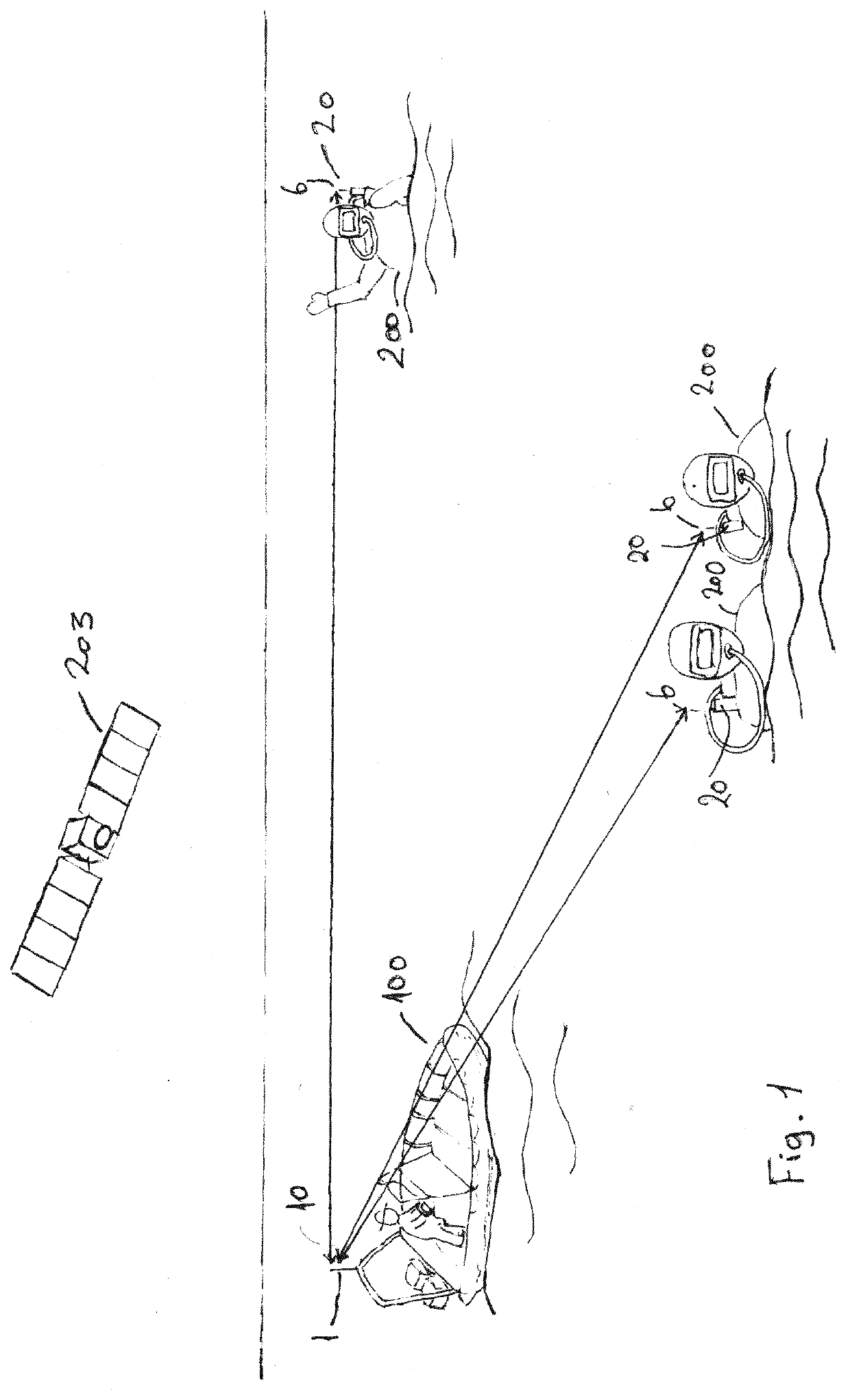
[0018]The invention provides a tracking system. In one embodiment the tracking system may be used to keep track of one or more divers during a diving expedition with one or more divers. This is an exemplary embodiment and the skilled person will appreciate that the tracking system will be useful for many other emergency and non-emergency applications such as man over-board, end of dive pick up, tracking personnel and assets on large area installations such as wind farms, solar farms, oil rigs large chemical and other factories, large construction projects etc. The invention could also be useful for other watersports such as sailing, canoeing, kayaking.

[0019]The embodiment provides an aid to the boat crew to recover divers quickly at the end of a dive, minimising the time spent by the waiting divers in the water, and reducing the risk of divers becoming separated from their boat

[0020]An embodiment will now be described, by way of example only, with reference to the accompanying drawi...


PUM


Abstract

The invention relates to a tracking system and method comprising: a first and second tracking units comprising a satellite signal receiver, a microprocessor, a radio frequency (RF) transmitter and receiver; and an indicator means; and in which upon activation of the first unit, the first unit satellite signal receiver is arranged to receive satellite signals and to determine a location of the first unit. The first unit microprocessor is arranged in operation to receive the location from the first unit satellite signal receiver and generate a first unit location signal in dependence upon said location; and the first unit RF transmitter is arranged to transmit said signal; the second unit is arranged to receive satellite signals and calculate a second unit location; the second unit microprocessor is arranged in operation to receive the second unit location from the second unit satellite receiver. The second unit RF receiver is arranged to receive said first unit location signal; and the second unit microprocessor is arranged upon receipt of said first unit location signal to determine the first unit location; and determine a bearing and distance in dependence upon the first unit location and the second unit location; and indicate said bearing and distance on said second unit indicator means. The first tracking unit also includes a line of sight obstruction detecting means for detecting the presence of nearby obstructions, a height position determining means for determining the relative height of the first tracking unit, wherein the microprocessor includes means of calculating, with reference to a time source, an optimum communications window to transmit and receive an RF signal in the future, based on the detected nearby obstructions, if any, the height position data, and calculated predicted values for the wave height and period, and sends an instruction to the RF transmitter to transmit a signal in the optimum communications window.

Description

[0001]The present invention relates to a tracking system, in particular for tracking persons, in particular divers, but also vehicles or other items.BACKGROUND OF THE INVENTION[0002]Tracking systems are known based on cellular mobile networks but these have limitations on the accuracy of the location of the tracked device and are also not useful in remote areas or environments where there is no cellular mobile network.[0003]Various different emergency positioning beacons exist and whilst they are all helpful in generally enabling a distress signal to be transmitted, each have a number of performance shortfalls from the perspective of both the crew and any search and rescue organisation seeking to respond to the emergency incident. They can only be used in an emergency, not for continuously tracking people who are not in an emergency but are in a potentially dangerous situation.[0004]In recent years, concentrated focus on safety issues by the appropriate regulating bodies in the mari...

Claims


Application Information

Patent Timeline
IPC IPC(8): G01S19/51G01S19/19H04W4/029H04W4/80H04W4/90H04B17/318
CPCG01S19/51G01S19/19H04B17/318H04W4/80H04W4/90H04W4/029B63C2009/0017
Inventor EDWARDS, CHRISTINEHALL, PETER
Owner SCI TECH POB
Why Eureka
Try Eureka