Intelligent environmental sensor for irrigation systems

a technology of intelligent environmental sensors and irrigation systems, applied in the direction of electric programme control, program control, instruments, etc., can solve the problems of unreliable and inconvenient, over-watering and under-watering of landscaping, and inability to effectively change the control parameters

Active Publication Date: 2006-03-07
TORO CO THE
View PDF22 Cites 117 Cited by
  • Summary
  • Abstract
  • Description
  • Claims
  • Application Information

AI Technical Summary

Benefits of technology

[0013]c) a switch for conveying the control signals from the control element to the irrigation system via the irrigation system interface, for either permitting or prohibiting watering by the irrigation system, responsive to the control signals generated by and received from the control element.

Problems solved by technology

At most times this proves to be unreliable and inconvenient due to inconsistencies by the operator.
This leads to over-watering and under-watering of the landscaping.
One drawback of currently available rain sensors is the inability to effectively change the control parameters for choosing the environmental conditions for allowing or suspending watering by the irrigation system.
Existing systems have some major disadvantages in that typical rain sensors are factory pre-set for the environmental conditions for allowing or suspending watering by the irrigation system or are only adjustable at the remote sensing location.
However, once installed and adjusted, rain sensors do not allow for parameter adjustments to be made by an individual at the irrigation controller.
Also, existing systems are not able to interpret the input received from the sensor.
The extent by which existing systems can be controlled is limited to sensitivity adjustments of the sensor unit such as for the amount of accumulated rainfall required to trip the sensor.
Also, typically, weather sensors are mounted where they are exposed to the elements and once mounted are not easily adjusted or manipulated.

Method used


Image

  • Intelligent environmental sensor for irrigation systems
  • Intelligent environmental sensor for irrigation systems
  • Intelligent environmental sensor for irrigation systems

Examples


Embodiment Construction

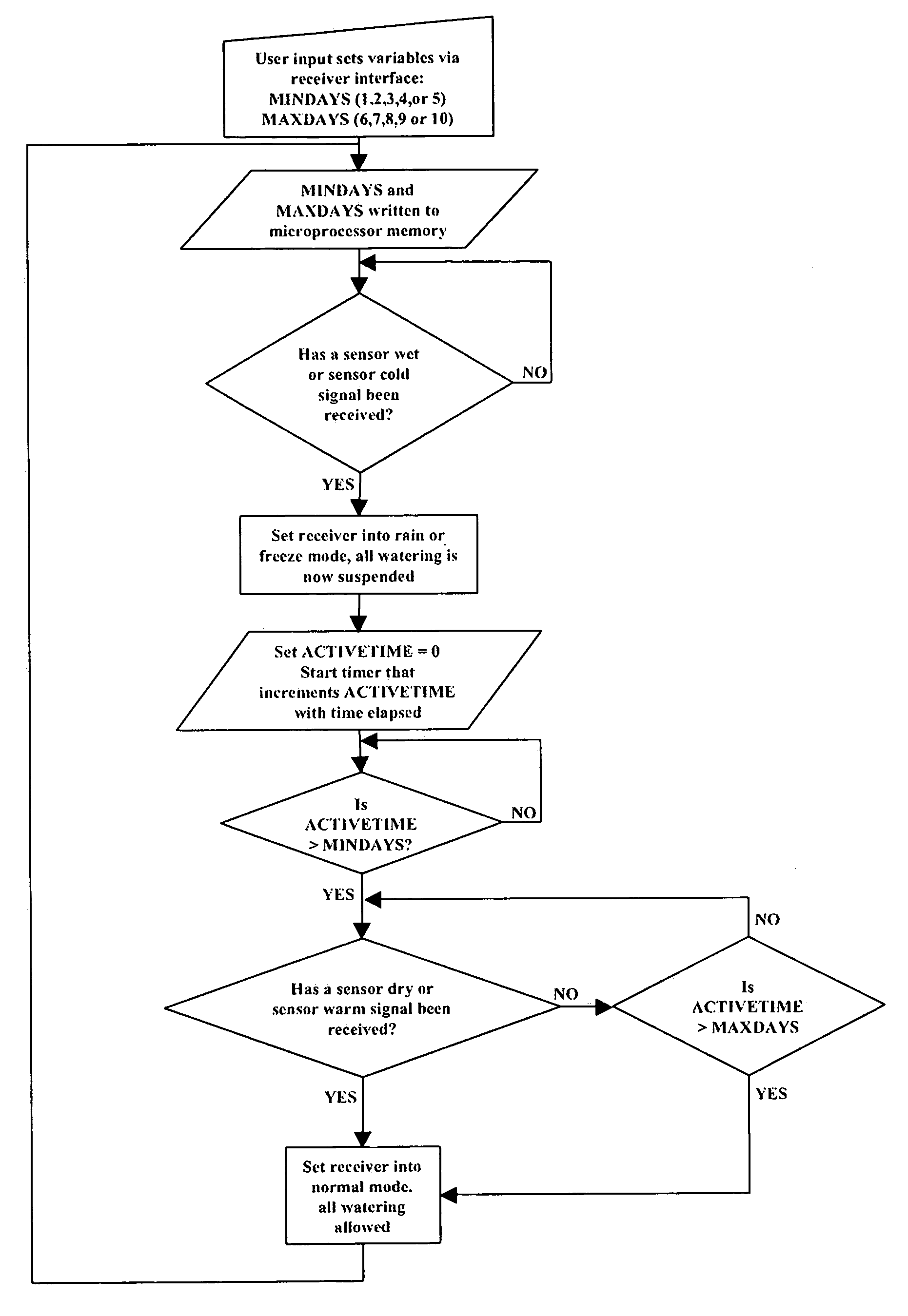
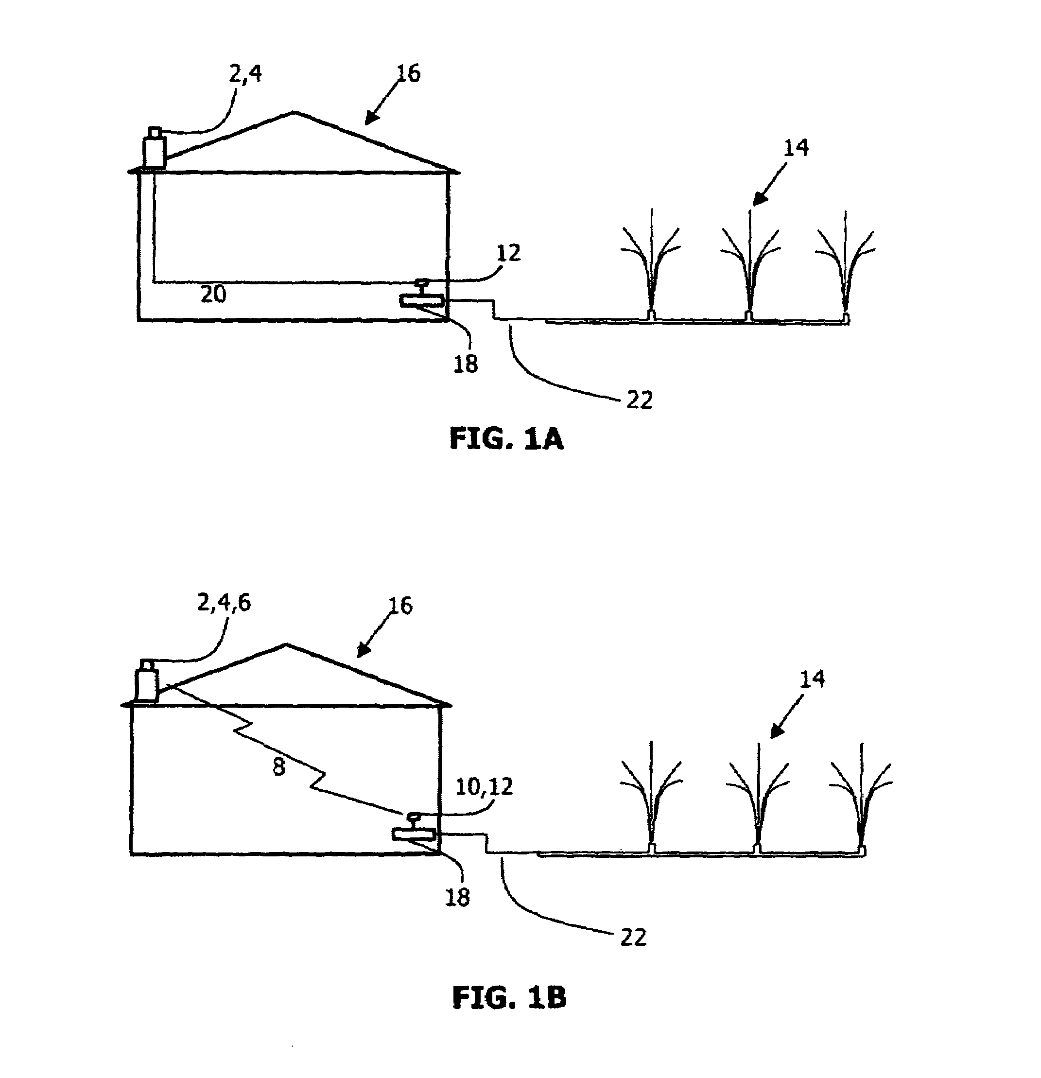
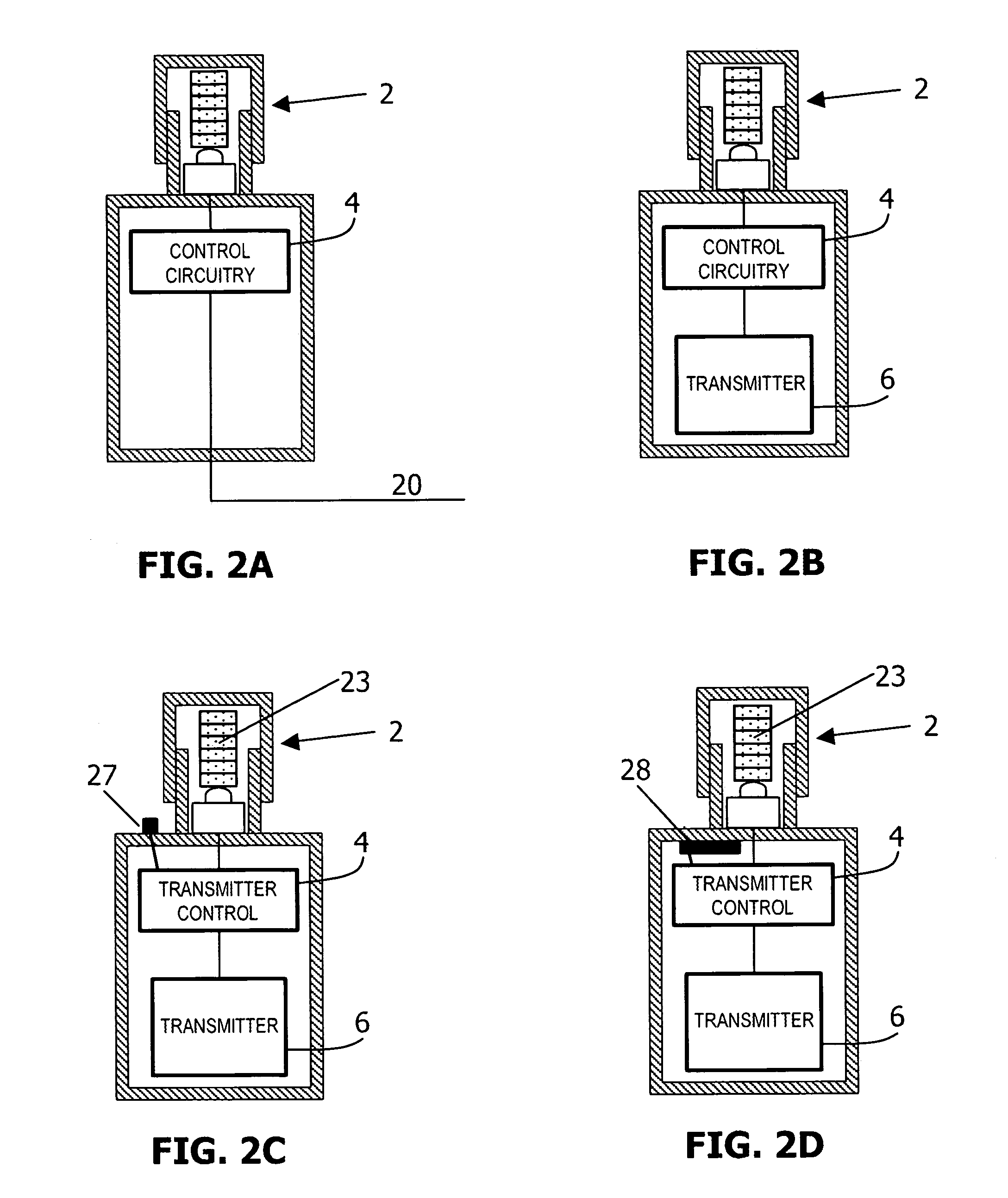
[0029]FIG. 6 shows a schematic representation of an irrigation regulator system according to the invention and its positioning with respect to an irrigation system and an optional irrigation system controller. The regulator system is shown to have a control element, a switch and an interface. The regulator system is either directly connected to the irrigation system or indirectly connected to the irrigation system through an intermediate irrigation system controller. Irrigation system controllers are well known in the art and serve to control water flow through the irrigation system tubing, valves and spray heads, usually on a timed, pre-programmed basis. The regulator system of this invention can either by-pass the controller and regulate the irrigation system directly, or in the preferred embodiment, the regulator operates to regulate the controller, and hence regulate the irrigation system indirectly through the controller.

[0030]The control element issues watering control signals...


PUM


Abstract

The invention provides a regulator system for regulating the operation of an irrigation system which is responsive to user programmed information. It has a control element for issuing watering control signals to an irrigation system, having at least one of (i) a duration programming device for programming a minimum amount of time and a maximum amount of time for the suspension of watering by the irrigation system, and (ii) a user adjustable temperature programming device for programming a minimum allowed temperature for initiating a watering period by the irrigation system. It further has an irrigation system interface for connecting said control element with the irrigation system. It also has a switch for conveying the control signals from the control element to the irrigation system via the irrigation system interface, for either permitting or prohibiting watering by the irrigation system, responsive to the control signals generated by and received from the control element.

Description

CROSS REFERENCE TO RELATED APPLICATION[0001]This application claims the benefit of U.S. Provisional patent application Ser. No. 60 / 421,613 filed Oct. 24, 2002.BACKGROUND OF THE INVENTION[0002]1. Field of the Invention[0003]The present invention relates to a system for regulating the operation of an irrigation system. More particularly, the invention pertains to a regulator system for regulating the operation of an irrigation system which is responsive to user programmed information.[0004]2. Description of the Related Art[0005]Automatic irrigation systems such as those employed for landscape and agricultural watering are well known in the art. Typical irrigation systems use a means of controlling the watering cycles via an automatic controller. The need to control watering cycles due to environmental conditions is important for saving costs and preventing unsafe conditions. Watering cycle controls must be responsive to precipitation, high wind and freezing temperature situations. The...

Claims


Application Information

Patent Timeline
Patent Type & Authority Patents(United States)
IPC IPC(8): G05D7/00
CPCA01G25/167G05B19/05A01G25/16G05B2219/2625
Inventor RUNGE, THOMAS H.DOWNIE, BRUCE M.
Owner TORO CO THE
Why Eureka
Try Eureka