Stump grinder having automatic reversing feed assembly

a technology of automatic reversing and feed assembly, which is applied in the field of stump grinders, can solve the problems of stump grinder plugged or otherwise inoperable, engine stall or part failure, and higher cos

Active Publication Date: 2006-03-14
BANDIT IND
View PDF10 Cites 54 Cited by
  • Summary
  • Abstract
  • Description
  • Claims
  • Application Information

AI Technical Summary

Benefits of technology

[0012]One advantage of the present invention is that an automatic reversing feed assembly is provided for a stump grinder. Another advantage of the present invention is that the automatic reversing feed assembly reverses operational movement of the cutting assembly relative to the stump when an excessive load is placed on the stump grinder. Yet another advantage of the present invention is that the automatic reversing feed assembly reverses the cutting assembly when an excessive load is placed on the stump grinder, waits, and restarts the feed direction of the cutting assembly once the excessive load is terminated. A further advantage of the present invention is that the automatic reversing feed assembly includes a control system that can be used with an actuating assembly that is powered hydraulically, electronically, or pneumatically.

Problems solved by technology

Exerting too much force against the stump will slow the rotation of the cutting assembly and overwork the engine, which may result in engine stall or part failure.
When the engine stalls or a part fails, the stump grinder may become plugged or otherwise inoperable.
This is a relatively time consuming and labor intensive process, resulting in higher costs, which is undesired.
Conversely, exerting too little force against the stump will under-work the engine, resulting in a more time consuming process and a loss of productivity, resulting in higher costs.
However, an operator's sensory perception is highly subjective relative to one's skill / experience, ambient conditions, and stump condition, thus, subject to a loss of maximum efficiency.
One disadvantage of the above stump grinding machine is that the advancement of the stump cutter toward a stump is continued, albeit at a slower rate, when the engine speed begins to decrease.
Despite the slower rate, an excessive load may continue to be placed on the engine, which can result in engine stall or component failure.
Further, this type of stump grinder also suffers from the disadvantage of delaying engine recovery time since the cutter is still in contact with the stump although at a lower feed rate.
Maintaining stump contact when engine speed is decreased may result in engine stall or part failure.

Method used


Image

  • Stump grinder having automatic reversing feed assembly
  • Stump grinder having automatic reversing feed assembly
  • Stump grinder having automatic reversing feed assembly

Examples


Embodiment Construction

)

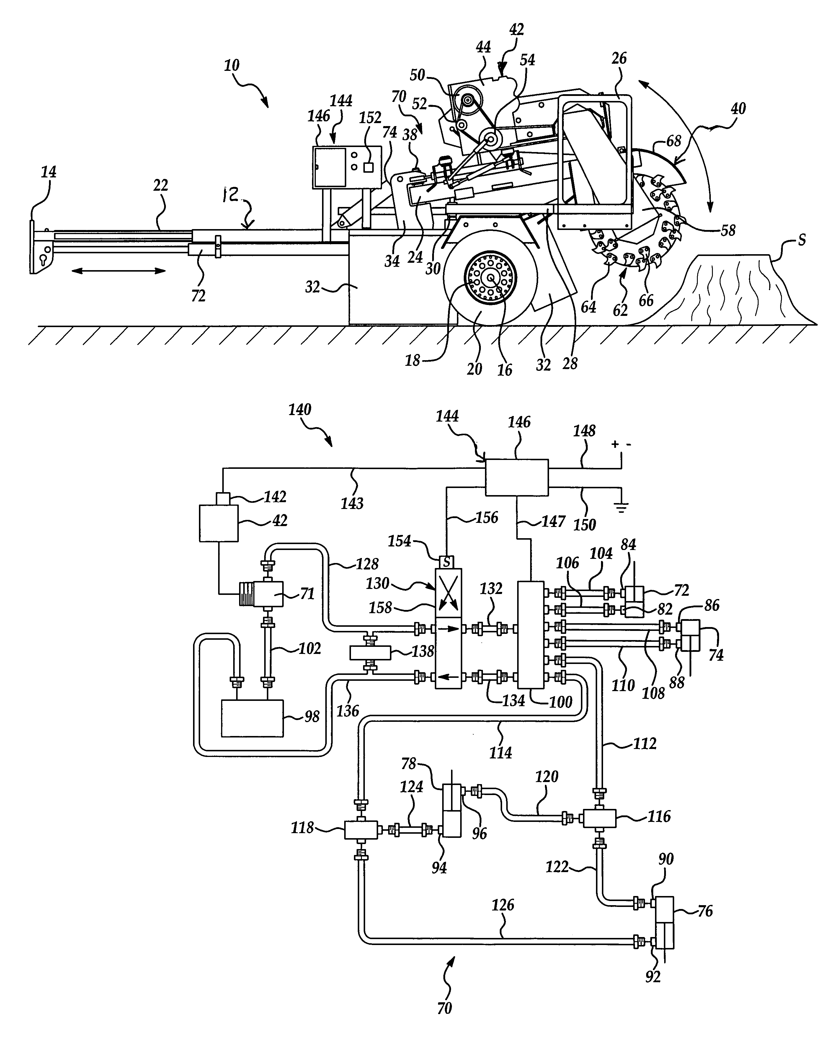
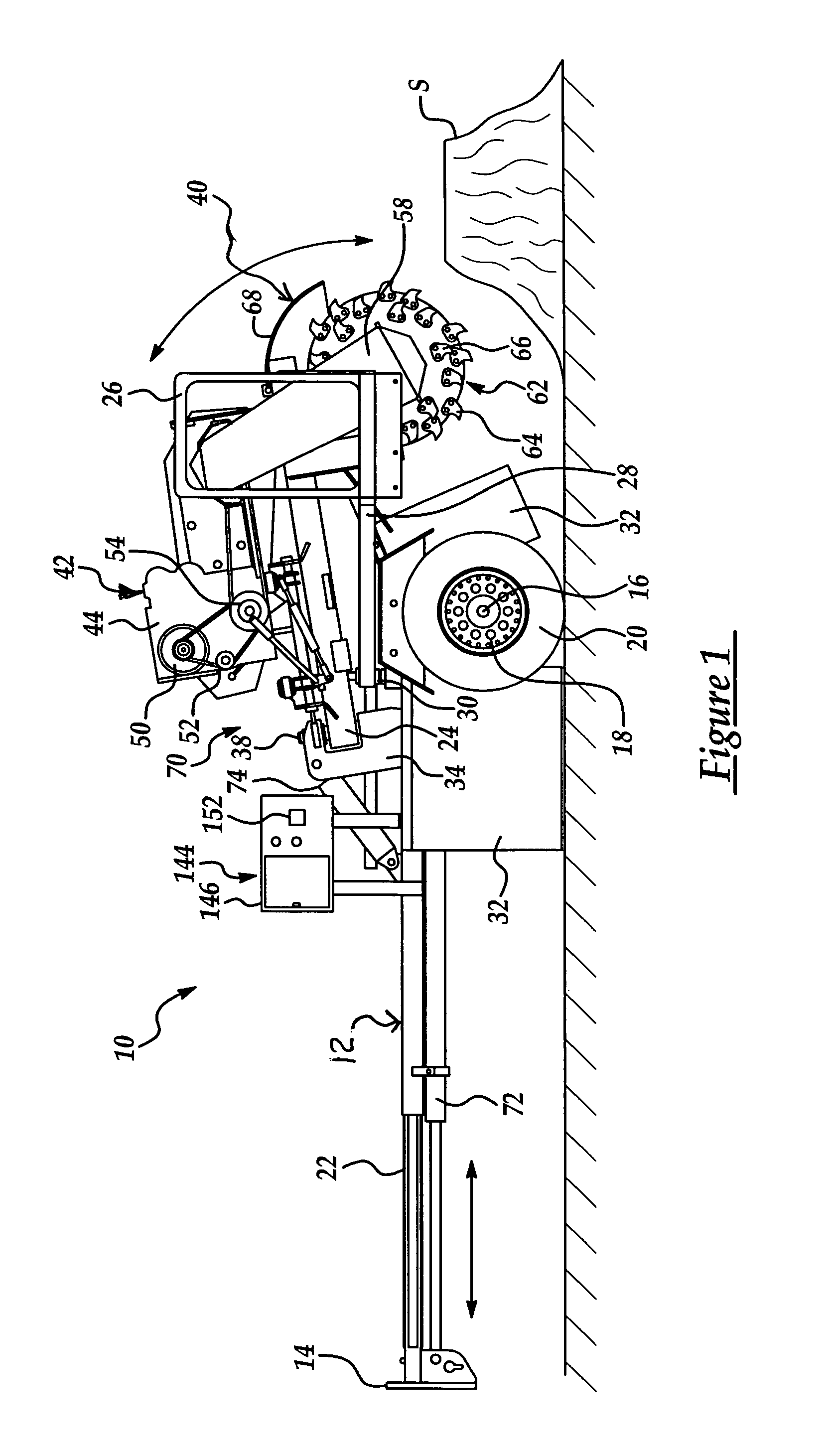
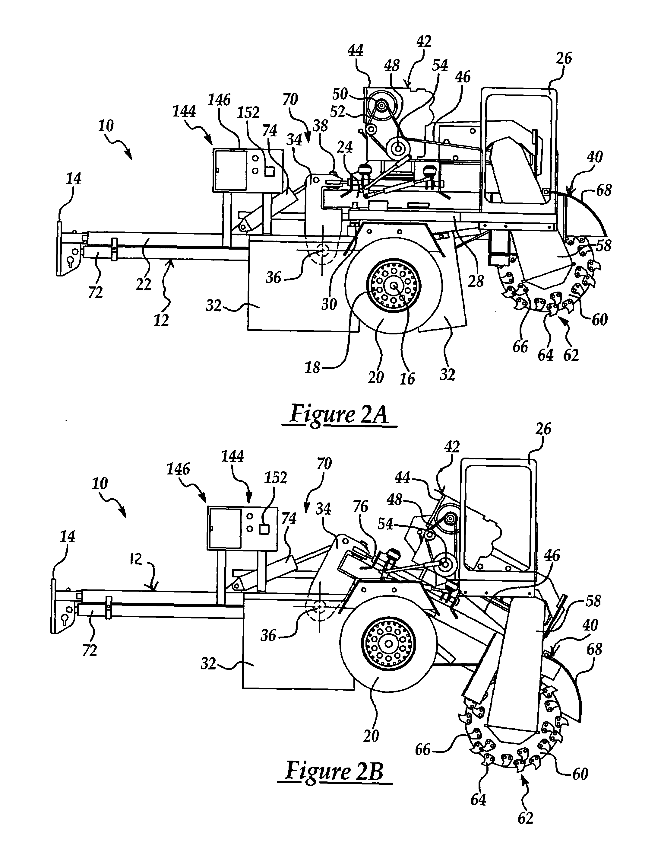
[0020]Referring now to the drawings and in particular FIGS. 1 through 3A, one embodiment of a stump grinder 10, according to the present invention, is shown. The stump grinder 10 includes a frame, generally indicated at 12. The frame 12 extends longitudinally. The stump grinder 10 includes a hitch assembly 14 at one longitudinal end of the frame 12 to receive a hitch of a vehicle (not shown) for towing behind a vehicle. The stump grinder 10 also includes an axle 16 rotatably supported by the frame 12, wheel rims 18 operatively connected to the axle 16, and tires 20 attached to the wheel rims 18 to facilitate movement of the stump grinder 10 during transportation and movement relative to a stump (S).

[0021]As illustrated in FIGS. 1 through 3A, the frame 12 includes a first or lower section 22 and a second or upper section 24 operatively supported by the lower section 22. The lower section 22 includes an operational viewing window 26 and an arm 28 pivotally mounted relative to the fra...


PUM


Abstract

A reversing automatic feed assembly for a stump grinder includes at least one sensor adapted to sense excessive load placed on the stump grinder and output a signal thereof. The reversing automatic feed assembly also includes a control system operatively connected to the least one sensor to automatically reverse feed movement of the cutting assembly in response to the signal from the at least one sensor.

Description

BACKGROUND OF THE INVENTION[0001]1. Field of the Invention[0002]The present invention relates generally to stump grinders and, more particularly, to a stump grinder having an automatic reversing feed assembly.[0003]2. Description of the Related Art[0004]It is known to provide a stump grinder for grinding undesirable tree stumps. Typically, a stump grinder includes a frame, an engine or other drive mechanism such as a belt tension engagement mounted to the frame, a cutting assembly having a boom pivotally secured to the frame, and a rotatable cutting wheel operatively supported by the boom and driven by the engine. The stump grinder also includes an actuating assembly to move the stump grinder and / or cutting assembly relative to the stump and a control system to control the direction and rate of movement of the actuating assembly. Such actuating assemblies are typically hydraulic in nature, but may also be pneumatic, electronic, or mechanical.[0005]During removal of a tree stump from...

Claims


Application Information

Patent Timeline
Patent Type & Authority Patents(United States)
IPC IPC(8): A01G23/06B23Q15/013
CPCA01G23/067
Inventor MOREY, MICHAEL BOYD
Owner BANDIT IND
Why Eureka
Try Eureka