Position adjustment device for steering handle

a technology of positioning adjustment and steering handle, which is applied in the direction of steering column, steering parts, vehicle components, etc., can solve the problems of dampening impact, difficult to install stopper materials in a controlled manner by suitable pressure fittings, and impaired steering feel, so as to improve shock absorption performance, and improve assembly performance

Inactive Publication Date: 2006-03-14
YAMADA SEISAKUSHO KK
View PDF9 Cites 8 Cited by
  • Summary
  • Abstract
  • Description
  • Claims
  • Application Information

AI Technical Summary

Benefits of technology

[0011]A third aspect of the present invention provides a position adjustment device for a steering handle, comprising: a fixed bracket 20; a movable bracket A; a bolt shaft section 13 for coupling said fixed bracket 20 and movable bracket A; and a collar member B that is installed between respective supporting side sections1, 1 of the movable bracket A that are mutually opposing in the lateral direction thereof, the collar member B being formed into a folded shape from a lower supporting plate section 5 and upper supporting plate section 6 that are mutually opposing in a parallel fashion and combined together with a coupling plate 9, and the collar member B being provided with an end plate 10 formed integrally with the upper supporting plate section 6 on the side opposite to that of the coupling plate 9, and further provided with a second fitting section 14 consisting of a left and right pair of hook-shaped projecting pieces 14a, 14a comprising vertical projecting pieces 14a1, 14a1 formed at the lower end and at the laterally opposite sides of the end plate, and horizontal projecting pieces 14a2, 14a2 projecting inwards from the vertical projecting pieces 14a1, 14a1 respectively; and a stopper buffering material D, the respective side locations of the stopper buffering material D in the lateral direction thereof being firmly fitted with the hook-shaped pieces 14a, 14a of said second fitting section 14. Therefore, since respective side locations of the stopper buffering material D are fixed by the left and right-hand pair of hook-shaped fitting pieces 14a, 14a, then the holding characteristics of the stopper buffering material D are increased, durability with respect to shocks is improved, and the material can be prevented from becoming detached readily.
[0012]A fourth aspect of the present invention provides the position adjustment device for a steering handle according to the third aspect, wherein a first fitting section 11 comprising a constricted section 11a and a fitting projection 11b formed to a greater width than the constricted section 11a is formed from the lower end of the end plate 10, at an approximately central position with respect to the two hook-shaped fitting pieces 14a, 14a of the second fitting section 14, and the stopper buffering material D fits with and fixes to the first fitting section 11 and second fitting section 14; and hence the stopper buffering material D is fitted with and fixed by the first fitting section 11 and the second fitting section 14, and this stopper buffering material D becomes difficult to detach from the end plate 10, thereby making it possible to achieve a very strong and durable state of installation.
[0013]A fifth aspect of the present invention provides the position adjustment device for a steering handle according to the third aspect, wherein a vertical guide piece 14b is formed between the two hook-shaped projecting pieces 14a, 14a of respective second fitting sections 14, the vertical guide piece 14b being inserted freely into a fitting through hole 18 of the stopper buffering material D; and hence a structure is achieved wherein the stopper buffering material D can readily be fitted with and fixed by the second fitting sections 14, 14, and hence assembly characteristics can be improved.
[0014]A sixth aspect of the present invention provides the position adjustment device for a steering handle according to the first, second, third, fourth or fifth aspects, wherein an auxiliary fitting section 12 is formed in the coupling plate 9 of the collar member B, an installation hole 5a is formed in the lower supporting plate section 5 in the vicinity of the region wherein the first fitting section 11 is formed, and an auxiliary stopper buffering material D1 having a smaller width than that of the stopper buffering material D is installed on the auxiliary fitting section 12; and therefore a stopper buffering material D and an auxiliary stopper buffering material D1 can be installed on the front and rear ends of the collar member B, thus making it possible further to improve the shock absorbing function.
[0015]A seventh aspect of the invention provides the position adjustment device for a steering handle according to the first, second, third, fourth or fifth aspects, wherein the stopper buffering material D comprises abutment sections 15 abutting against the bolt shaft section 13, formed symmetrically in an approximately parallel fashion at a suitable interval apart, a fitting through hole 18 capable of fitting with the first fitting section 11 or the auxiliary fitting section 12 being formed between the respective abutment sections 15, 15; and hence the operability of installing the stopper buffering material D on the first fitting section 11 or the auxiliary fitting section 12 is improved. Here, the stopper buffering material D (including the auxiliary stopper buffering material D1) comprises two abutment sections 15, 15, which are formed symmetrically in an approximately parallel fashion at a suitable interval apart, a fitting through hole 18 being formed in the two opposing abutment regions 15, 15.
[0016]Therefore, when a stopper buffering material D is fitted with and installed on the first fitting section 11 (or the auxiliary fitting section 12) of the collar member B, it can be installed without any limitation of the direction in which the stopper buffering material D is attached, and hence the ease of the task is improved. Moreover, since one of the abutment sections 15 abuts with the bolt shaft section 13 when the stopper buffering material D has been installed on the collar member B, then even if the stopper buffering material D is used over a long period of time and this one abutment section 15 wears, since the abutment section 15 on the other side is unused, if the stopper buffering material D is removed temporarily from the collar member B, the orientation thereof changed, and the other abutment section 15 made to abut with the bolt shaft section 13, then the stopper buffering material D can be used over a yet longer period of time.

Problems solved by technology

Since there is a metallic contact between the lock lever shaft and the long groove end portion of the members, the steering feel is impaired by the occurrence of the impact type abutment in the stopper.
Consequently, there have been cases where a stopper material made from rubber, synthetic resin, or the like, is installed at the position of abutment with the lock lever shaft, thereby dampening the impact.
However, if pressure fitting is adopted for the installation structure of the stopper material, then it is difficult to install the stopper material in a controlled manner by suitable pressure fitting, on a plate shaped installation section of a collar.
Moreover, if the pressure fitting load is small, then although installation characteristics are improved, the material becomes more liable to detachment, due to shocks, or the like.
Furthermore, since a steering device generally comprises a large number of components packed into a small space, then the task of installing the stopper material is very troublesome, and if the pressure fitting load is large, then the installation characteristics are further impaired.

Method used


Image

  • Position adjustment device for steering handle
  • Position adjustment device for steering handle
  • Position adjustment device for steering handle

Examples


Embodiment Construction

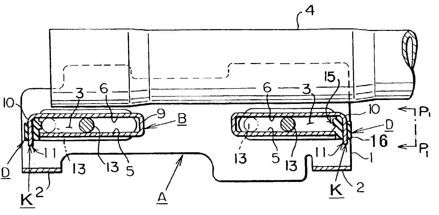
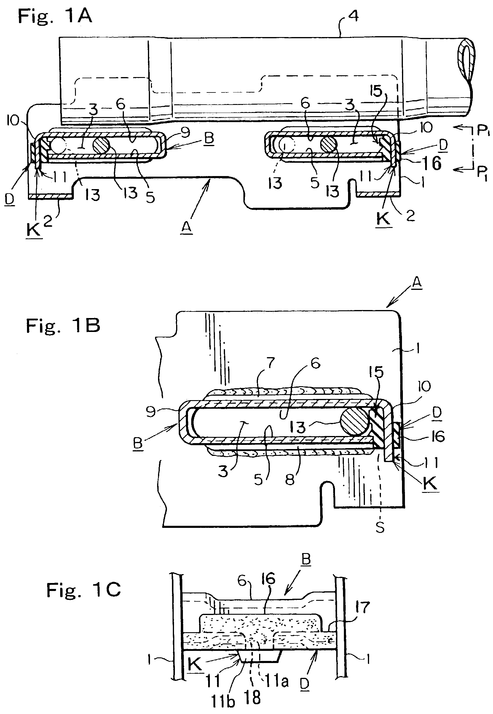
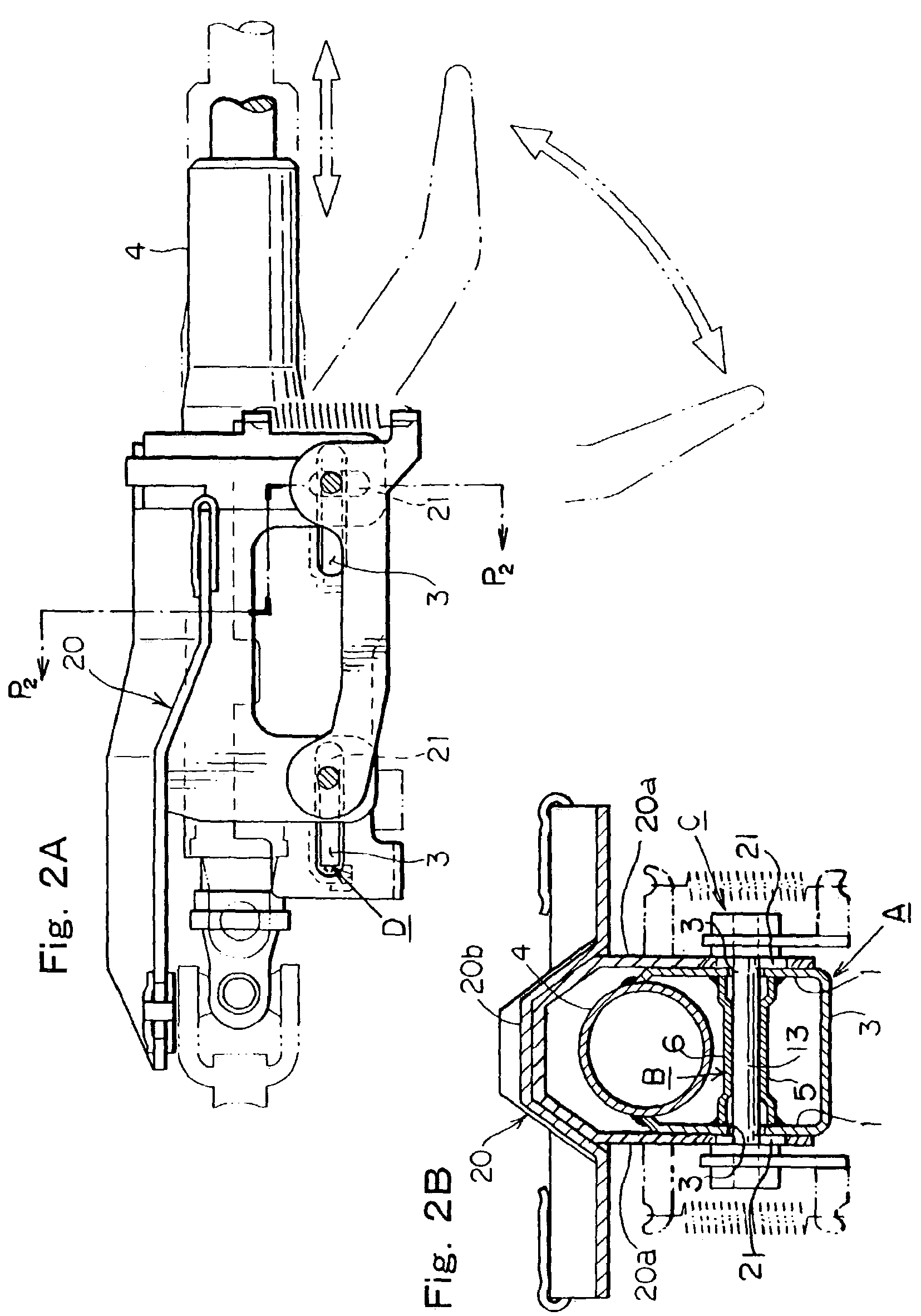
[0047]Below, embodiments of the present invention are described with reference to the drawings. Firstly, as illustrated in FIG. 1A, FIG. 2, and the like, the present invention is principally constituted by a fixing bracket 20, a movable bracket A, a collar member B, and a lock lever shaft C. Firstly, the fixed bracket 20 is constituted by a pair of left and right-hand fixed supporting side plates 20a, 20a, and an attached top section 20b. The attached top section 20b is installed at a prescribed position on the vehicle via capsule members, in such a manner that it is able to absorb impact energy.

[0048]The movable bracket A is formed with supporting side sections 1, 1 on either side thereof in the lateral direction. The two supporting side sections 1, 1 are formed with a bottom face section 2 which couples the supporting side sections 1, 1 together in a unified fashion, on the lower side thereof. The steering column 4 is fixed by welding, in a supported and sandwiched state, between ...


PUM


Abstract

An object of the present invention is to enable very easy installation of a stopper buffering material for absording impacts during tilt and telescopic adjustment, in a steering device having a tilt and telescopic adjustment mechanism, and to ensure that the stopper buffering material is not readily detachable, once installed. The present invention comprises: a fixed bracket; a movable bracket; a bolt shaft section; a collar member that is installed between respective supporting side sections of the movable bracket that are mutually opposing in the lateral direction thereof, the collar member being formed into a folded shape from a lower supporting plate section and upper supporting plate section that are mutually opposing in a parallel fashion and combined together with a coupling plate, and the collar member being provided with an end plate formed integrally with the upper supporting plate section on the side opposite to that of the coupling plate, and further provided with a fitting section formed at the lower end of the end plate; and a stopper buffering material, the stopper buffering material being fixed to the end plate of the collar member.

Description

BACKGROUND OF THE INVENTION[0001]1. Field of the Invention[0002]The present invention relates to a position adjustment device for a steering handle having a tilt / telescope adjustment mechanism, whereby a stopper buffering material for absorbing shocks when performing tilt / telescope adjustment can be installed very easily, and once installed, the stopper buffering material can be prevented from becoming readily detached.[0003]2. Description of the Related Art[0004]In the prior art, Japanese Laid-open Utility Model Publication No. S64-28365 discloses a position adjustment device for a steering handle wherein a pair of brackets are fixed integrally with a steering column at a uniform interval by means of spacers, a long groove being formed in the axial direction of the brackets and a lock lever shaft being inserted and positioned inside the long groove and the spacers.[0005]If the end members of a steering column are caused to move in the forward direction or backward direction of the ...

Claims


Application Information

Patent Timeline
Patent Type & Authority Patents(United States)
IPC IPC(8): B62D1/18B62D1/184
CPCB62D1/184
Inventor TSUJI, KATSUTOSHIIMAI, MASAYUKI
Owner YAMADA SEISAKUSHO KK
Why Eureka
Try Eureka