Balance with a T-shaped coupling arrangement that guides the support element onto a load receiver at three points forming a triangle

a coupling arrangement and support element technology, applied in the field of balance with a weighing cell, can solve the problems of unfavorable corner load behavior, harmful torque entering the weighing cell, danger, etc., and achieve the effect of convenient cleaning and low friction

Inactive Publication Date: 2006-03-14
METTLER TOLEDO GMBH
View PDF7 Cites 14 Cited by
  • Summary
  • Abstract
  • Description
  • Claims
  • Application Information

AI Technical Summary

Benefits of technology

[0008]The coupling arrangement, i.e., the arrangement to couple the support element to the load receiver of the weighing cell, has the particularly advantageous distinction that the guiding constraint of the support element on the load receiver is realized with rolling elements to reduce friction, in particular with rolling balls.
[0017]In particularly advantageous embodiments of the inventive balance, the floor of the weighing compartment has no openings of any kind. This makes the weighing compartment significantly more convenient to clean.

Problems solved by technology

Balances of this kind are prone to the risk that the forces acting on the cantilever element may cause a deformation of the vertically movable load receiver which, in turn, may introduce harmful torques into the weighing cell, specifically into the sensitive flexure pivots of the weighing cell.
This danger is present in particular when a load is placed at an off-center position on the weighing pan.
In the terminology of weighing instruments, the balance has an unfavorable cornerload behavior.
This creates the danger that deformations of the U-shaped support-arm arrangement are still introduced, albeit in attenuated form, directly into the load-receiving area of the weighing cell where they have an effect on the flexure joints.
Furthermore, the force that triggers the overload safety device is position-dependent.
Furthermore, the balance disclosed in DE-33 30 988 A1 offers no solution for the protection of the sensitive flexure pivots of the weighing cell against excessive vertical forces applied in the reverse direction to the force caused by a weighing load.

Method used


Image

  • Balance with a T-shaped coupling arrangement that guides the support element onto a load receiver at three points forming a triangle
  • Balance with a T-shaped coupling arrangement that guides the support element onto a load receiver at three points forming a triangle
  • Balance with a T-shaped coupling arrangement that guides the support element onto a load receiver at three points forming a triangle

Examples


Embodiment Construction

is presented below on the basis of exemplary embodiments of a balance according to the invention, specifically of a support element according to the invention, as illustrated in the drawings which represent simplified schematic views of the invention and wherein:

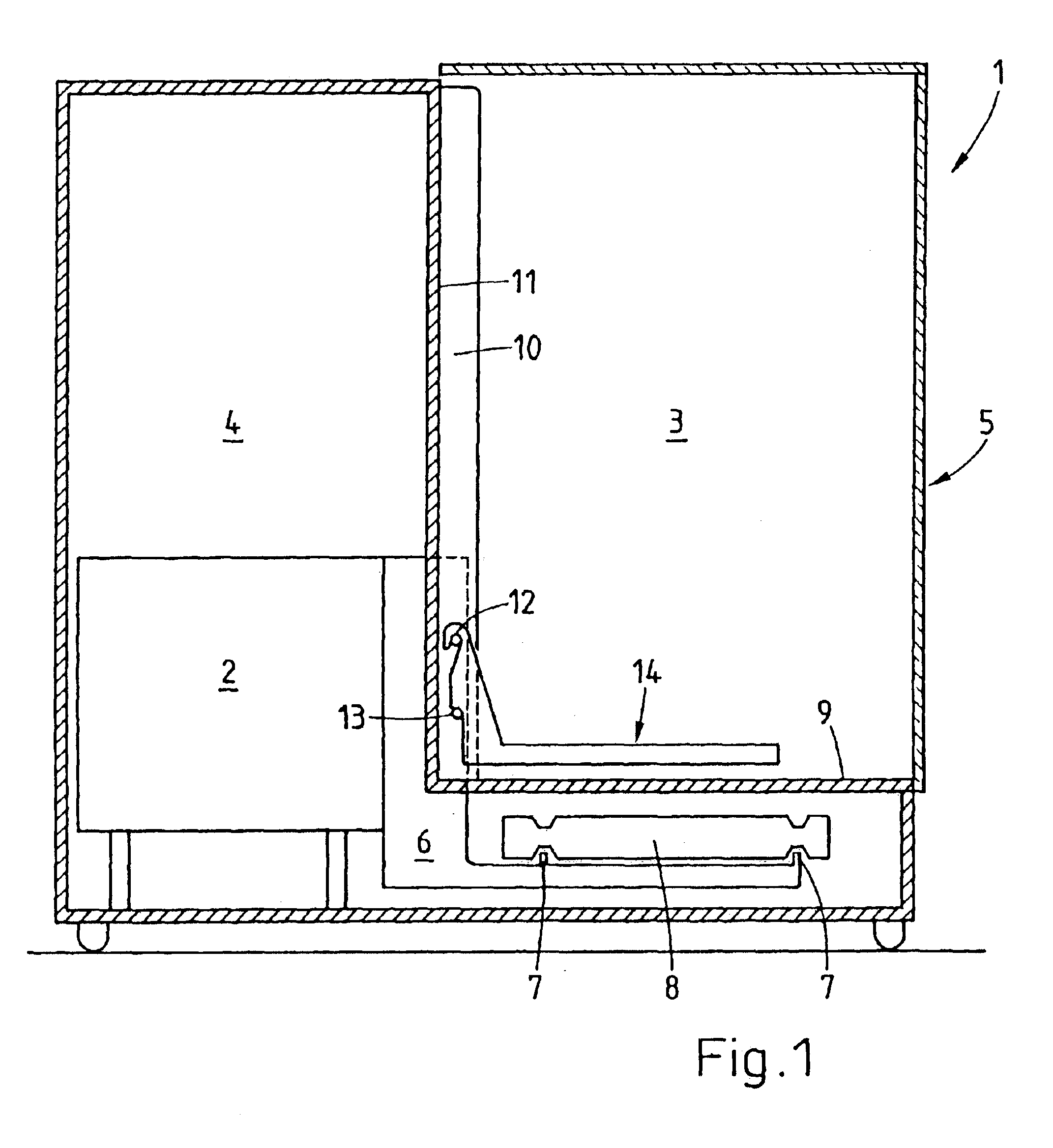
[0019]FIG. 1 represents a side view of the balance,

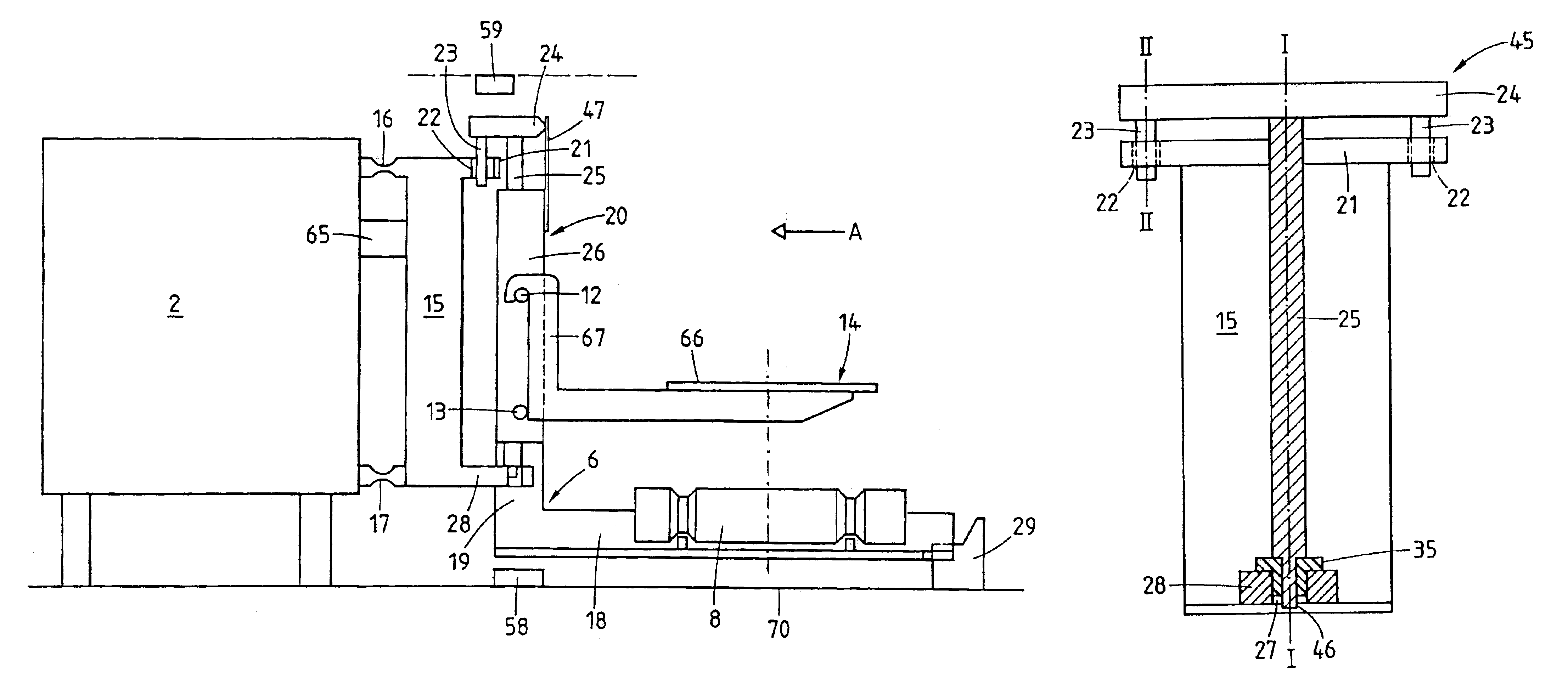
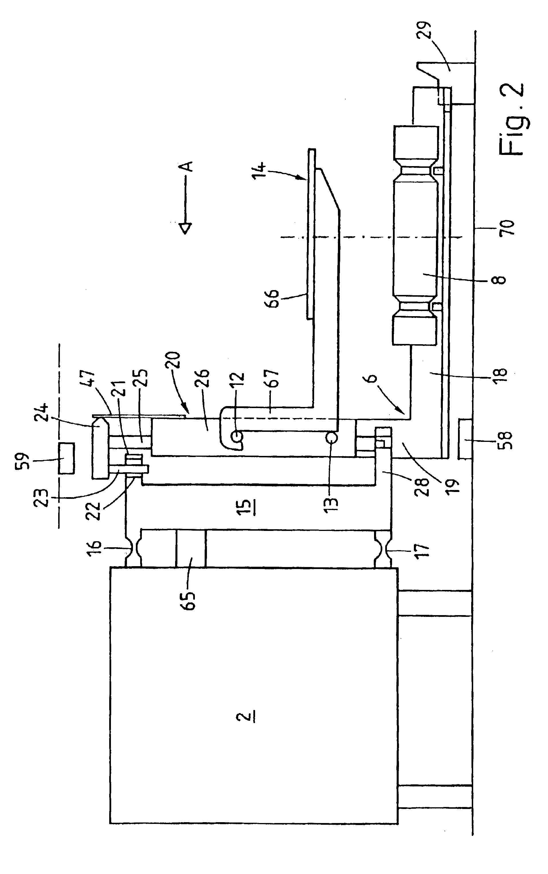
[0020]FIG. 2 represents a side view of a weighing cell, a support element with a cantilever arm, and a weighing pan carrier attached to the cantilever arm in a balance according to the invention,

[0021]FIG. 3 represents a coupling element supported in a suspended position from the upper projection of the load receiver, shown in a sectional view in a plane that is perpendicular to the arrow A of FIG. 2,

[0022]FIG. 4 shows the load receiver with the support element set in place, as seen from above,

[0023]FIG. 5 represents a top view of the load receiver without the support element,

[0024]FIG. 6a represents a simple embodiment of the load receiver without the support element in a t...


PUM


Abstract

A balance includes a weighing cell with a vertically movable load receiver, a weighing pan to receive a weighing load, and a support element to couple the weighing pan to the vertically movable load receiver of the weighing cell. A cantilever arm with a seat for at least one calibration weight is solidly connected to the support element. The balance has a coupling arrangement that constrains the support element with low-friction mobility to the load receiver at three points forming a triangle in a plane that extends orthogonal to the symmetry plane of the weighing cell, wherein the triangle is symmetric to the symmetry plane of the weighing cell. Under the coupling arrangement, the support element is solidly supported on the load receiver in the direction in which the weighing load is acting.

Description

BACKGROUND OF THE INVENTION[0001]The invention relates to a balance with a weighing cell including a vertically movable load receiver, with a weighing pan to receive the weighing load, and with a support element to couple the weighing pan to the vertically movable load receiver of the weighing cell, wherein a cantilever support with a seat for at least one calibration weight of a calibration device is solidly connected to the support element.[0002]Balances in which a cantilever element is connected to the weighing cell and in which a weighing pan and / or a calibration device is arranged at the opposite end of the cantilever from the connection to the weighing cell belong to the known state of the art. Balances of this kind are prone to the risk that the forces acting on the cantilever element may cause a deformation of the vertically movable load receiver which, in turn, may introduce harmful torques into the weighing cell, specifically into the sensitive flexure pivots of the weighi...

Claims


Application Information

Patent Timeline
Patent Type & Authority Patents(United States)
IPC IPC(8): G01G21/23G01G7/02G01G21/24G01G21/22G01G21/28G01G23/01G01G23/02
CPCG01G21/28G01G23/012Y10S177/09
Inventor LUDI, BEATFRINGELI, EDUARDLUCHINGER, PAUL
Owner METTLER TOLEDO GMBH
Why Eureka
Try Eureka