Vacuum fluorescent display device and the support of the cathode thereof

a fluorescent display and cathode technology, applied in the field of cathode support, can solve the problems of difficult to reduce the distance fw difficult to enlarge the display area, and difficult to save power and/or increase brightness, so as to reduce the distance between the cathode and the display area. , the effect of saving power

Active Publication Date: 2006-03-14
FUTABA CORPORATION
View PDF3 Cites 3 Cited by
  • Summary
  • Abstract
  • Description
  • Claims
  • Application Information

AI Technical Summary

Benefits of technology

The present invention provides a new type of cathode support that combines both its anchor and support functions into one structure. This design allows for larger displays, reduces the gap between cathodes and anodes (which saves energy), and prevents damage caused by direct transmission of vibrations during operation. These features make it easier to create more efficient and effective vacuum florescent display devices.

Problems solved by technology

The patent text describes a problem with the conventional vacuum fluorescent display device where the cathodes are supported by cathode supports that have a limited ability to save power and enlarge the display area. The technical problem is to develop a new cathode support that can save power and enlarge the display area without creating dead space. The new support includes a base, two arms, and a first and second supports seamlessly connected with the base. The distance between the cathodes and anodes can be reduced to improve brightness and power saving. However, the new support has areas where electrons cannot reach, resulting in no reduction in display area.

Method used


Image

  • Vacuum fluorescent display device and the support of the cathode thereof
  • Vacuum fluorescent display device and the support of the cathode thereof
  • Vacuum fluorescent display device and the support of the cathode thereof

Examples


Embodiment Construction

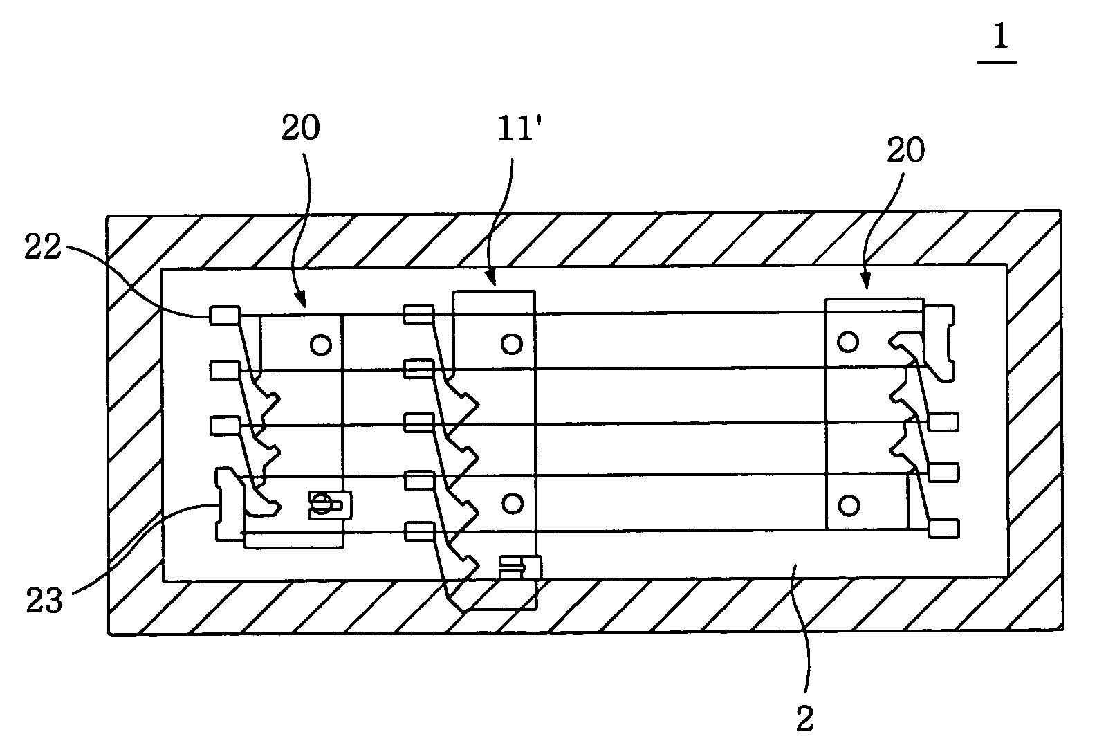
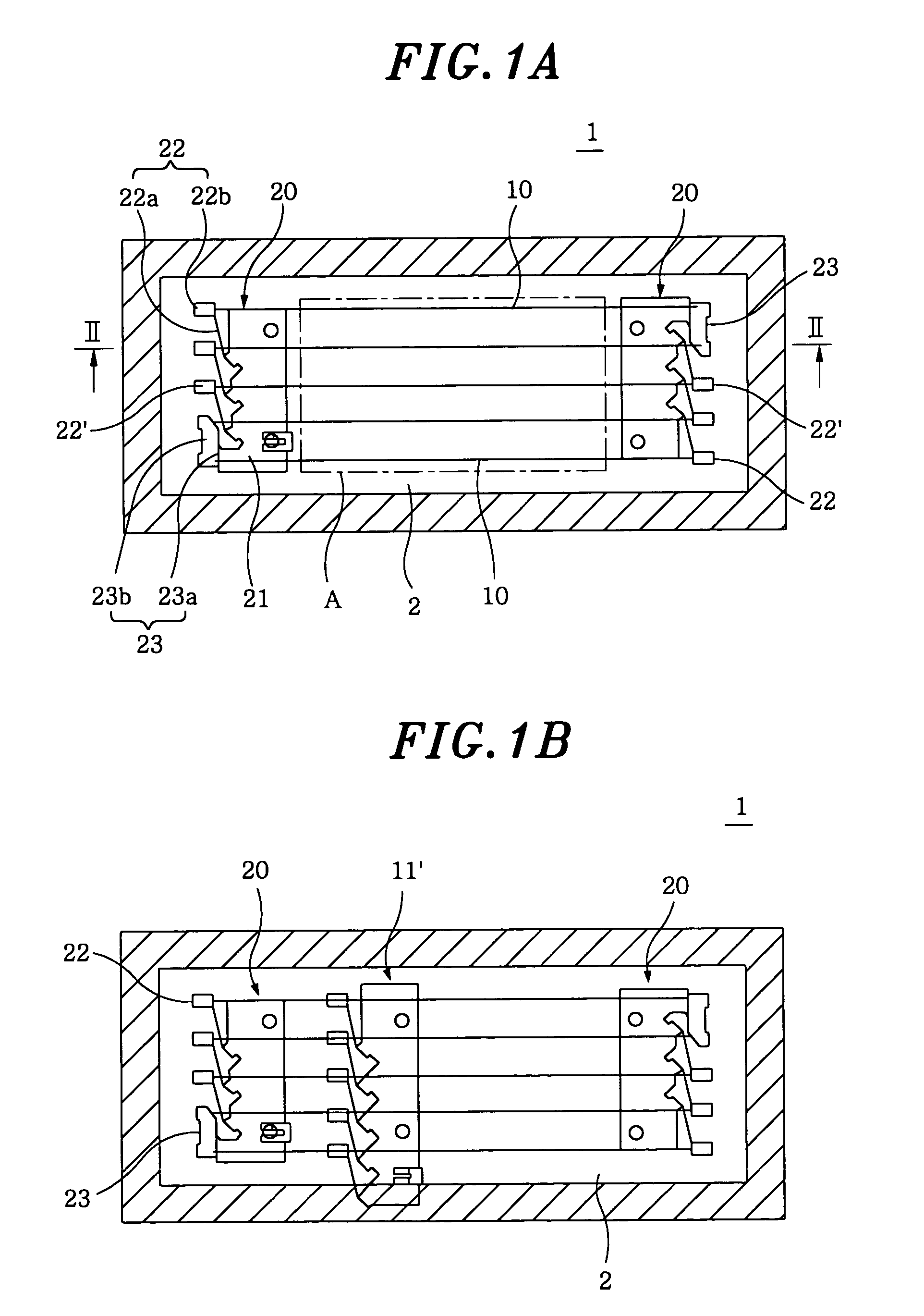
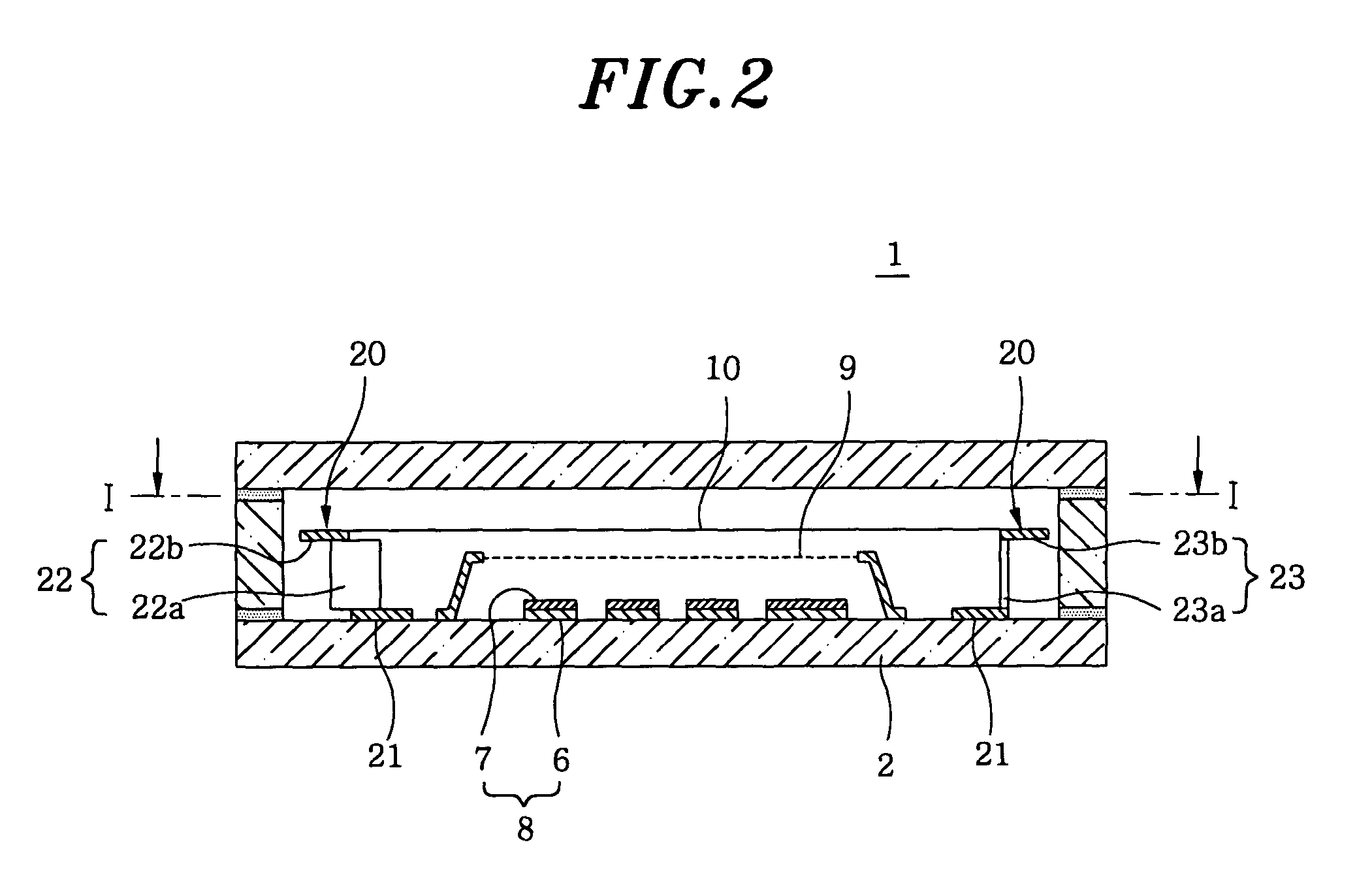
[0029]FIGS. 1A and 1B show cross-sectional top views of a vacuum fluorescent display device employing cathode supports 20 in accordance with a first preferred embodiment of the present invention. FIG. 2 illustrates a cross-sectional view taken along the line II—II in FIG. 1A. In FIGS. 1A and 1B, control electrodes 9 and anodes 8 shown in FIG. 2 are omitted for simplicity. FIG. 3 depicts a development view of a cathode support of the first embodiment. Herein, the vacuum fluorescent display device of the present invention is identical to a conventional vacuum fluorescent display device except for the configuration of the cathode supports.

[0030]Each of the cathode supports 20 in accordance with the first preferred embodiment of the present invention can be manufactured by cutting and bending a metal sheet having a thickness of about 0.05˜0.06 mm by using a press machine. A plurality of anchors 22 and 22′ are seamlessly formed with a base 21, which is fixed on an anode substrate 2, as s...


PUM


Abstract

A fluorescent display device includes an envelop of which an inner space is in a vacuum state. The envelop has therein a plurality of filament-shaped cathodes supported by a pair of cathode supports; and anodes, each having a fluorescent material, fluorescent materials of the anodes radiating light by impaction of electrons emitted from the cathodes. Each of the cathode supports includes a base fixed to the envelop; one or more anchors, each having an arm serving as a resilient member and a tab for supporting one end of a cathode, the arm having two opposite end portions, one end portion being connected to the base and the tab being disposed at the other end portion; and one or more support members, each being connected to the base and separated from an arm of its adjacent anchor and supporting one end of another cathode.

Description


Claims


Application Information

Patent Timeline
Owner FUTABA CORPORATION
Why Eureka
Try Eureka