Per zone variable BPI for improving storage device capacity and yield

a storage device and variable capacity technology, applied in the field of information storage, can solve the problems of yield of the disk drive, reducing the storage capacity, and conventional disk drives failing to account for the different capabilities of the head and the disk surface pair, so as to improve the storage capacity and yield, and reduce the test time

Inactive Publication Date: 2006-03-14
MAXTOR
View PDF9 Cites 50 Cited by
  • Summary
  • Abstract
  • Description
  • Claims
  • Application Information

AI Technical Summary

Benefits of technology

[0014]Advantageously, the present invention provides consistent performance (both sequential and random throughput) across a population of disk drives, improves storage capacity and yield and reduces test time.

Problems solved by technology

As data density increases, the head performance distribution also increases which diminishes disk drive storage capacity and yield.
Conventional disk drives fail to account for the different capabilities of the head and disk surface pairs.
This lowers storage capacity due to inefficient use of high performing head and disk surface pairs that can store more data, and lowers yield due to disk drives being scrapped if they include a low performing head and disk surface pair even if they also include a high performing head and disk surface pair.
U.S. Pat. Nos. 6,091,559 and 5,596,458 provide different BPI on different disk surfaces, however these approaches do not take into consideration multiple constraints, including head performance across the stroke per disk surface, performance requirements such as throughput and manufacturing requirements such as test time.

Method used


Image

  • Per zone variable BPI for improving storage device capacity and yield
  • Per zone variable BPI for improving storage device capacity and yield
  • Per zone variable BPI for improving storage device capacity and yield

Examples


example implementation

[0069]FIG. 2A shows a function and flow diagram for generating the optimal data density format shown in FIG. 1A. The function and flow diagram includes a data measurer 62, a post-measurement data processor 64, a format optimizer 66 and a format generator 68.

Data Measurer

[0070]The data measurer 62 takes data measurements for every zone at a finite number of frequency samples.

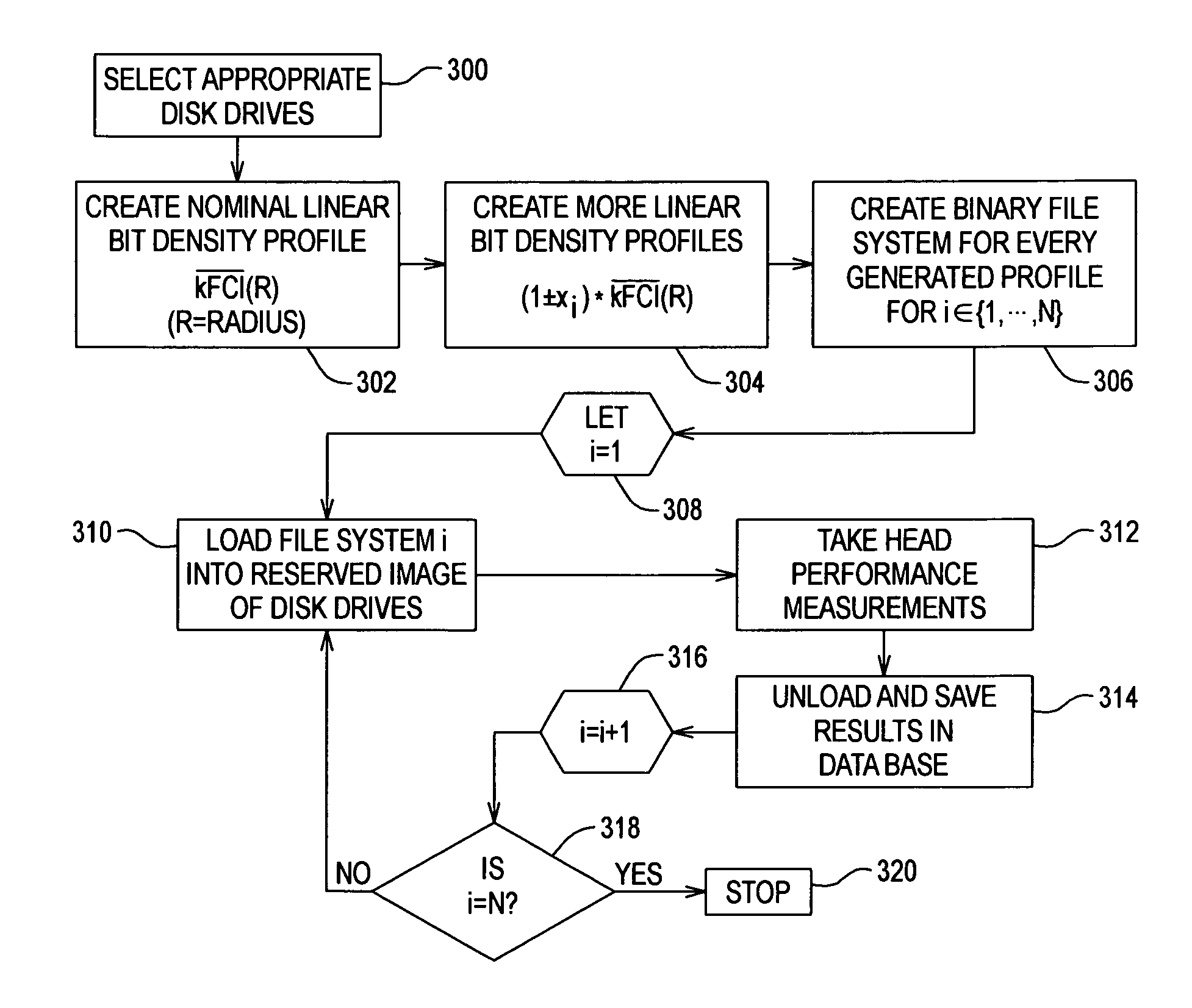
[0071]The data measurer 62 implements a measurement procedure that includes the steps of:[0072](1) Create several different predetermined linear bit density format profiles including a profile of different frequencies per zone across the stroke, such as a first profile including high frequency 1 for zone 1, high frequency 2 for zone 2 . . . high frequency M for zone M, and a second profile including low frequency 1 for zone 1, low frequency 2 for zone 2 . . . low frequency M for zone M to be loaded on a representative number of disk drives selected for the measurement process (or if possible on all the available ...


PUM

PropertyMeasurementUnit
ODaaaaaaaaaa
write frequenciesaaaaaaaaaa
frequenciesaaaaaaaaaa

Abstract

A method of defining such a storage format in multiple data storage devices, each data storage device having a plurality of storage media and a plurality of corresponding data transducer heads, each transducer head for recording on and playback of information from a corresponding storage medium in at least one zone, wherein each zone includes a plurality of concentric tracks for recording on and playback of information. The method includes the steps of: selecting a plurality of said data storage devices; for each selected data storage device, measuring a record/playback performance capability of each head at one or more read/write frequencies per zone; based on said performance capability measurements, generating storage density distributions corresponding to at least a number of the heads in said selected data storage devices; selecting a group of read/write frequencies for said multiple data storage devices, two or more frequencies for each zone, based on said storage density distributions; and assigning one of said read/write frequencies to each head based on performance capability of that head.

Description

FIELD OF THE INVENTION[0001]The present invention relates to information storage on a storage media such as a disk in a disk drive.BACKGROUND OF THE INVENTION[0002]Data storage devices such as disk drives are used in many data processing systems. Typically a disk drive includes a magnetic data disk having disk surfaces with concentric data tracks, and a transducer head paired with each disk surface for reading data from and writing data to the data tracks.[0003]Disk drive storage capacity increases by increasing the data density (or areal density) of the data stored on the disk surfaces. Data density is the linear bit density on the tracks multiplied by the track density across the disk surface. Data density is measured in bits per square inch (BPSI), linear bit density is measured in bits per inch (BPI) and track density is measured in tracks per inch (TPI). As data density increases, the head performance distribution also increases which diminishes disk drive storage capacity and ...

Claims


Application Information

Patent Timeline
Patent Type & Authority Patents(United States)
IPC IPC(8): G11B27/36
CPCG11B20/1258G11B27/36G11B2220/2516G11B2020/1292G11B2020/1275
Inventor ASGARI, SAEEDVEA, MATHEWISZLAI, GEORGE
Owner MAXTOR
Why Eureka
Try Eureka