Method for detecting emitted acoustic signals including signal to noise ratio enhancement

a technology of emitted acoustic signals and enhancement methods, applied in the field of detecting emitted acoustic signals including signal to noise ratio enhancement, can solve the problems of interfere with the performance of acoustic receivers, prior art signal models and detection methods have not performed satisfactorily when applied to detecting, and many efforts have not addressed important practical problems, to achieve the effect signal to noise ratio, and enhancement of signal to noise ratio

Inactive Publication Date: 2006-03-14
ALLIEDSIGNAL INC
View PDF1 Cites 9 Cited by
  • Summary
  • Abstract
  • Description
  • Claims
  • Application Information

AI Technical Summary

Benefits of technology

[0007]This invention contemplates a method for detecting emitted acoustic signals including signal to noise ratio enhancement, wherein the emitted signals are distinguished from self-noise transient signals. Since the emitted signals are unsteady, the present invention features an adaptive filter technique having the capability to track the emitted signal and to enhance the signal to noise ratio, as is desired. An adaptive tu...

Problems solved by technology

However, much of this effort has not addressed three important practical issues: (1) how low the signal to noise ratio is (less than −10 dB); (2) the existence of self-noise transient signals; and (3) the presence of strong tonals.
Therefore, prior art signal models and detection methods have not performed satisfactorily when applied to detecting, for example, actual underwater acoustic signals.
Due to various underwater biological effects and flow induced resonances, self-noise transient signals can also interfere with the performance of the acoustic receiver.
Existence of self-noise transient signals is a major factor whic...

Method used


Image

  • Method for detecting emitted acoustic signals including signal to noise ratio enhancement
  • Method for detecting emitted acoustic signals including signal to noise ratio enhancement
  • Method for detecting emitted acoustic signals including signal to noise ratio enhancement

Examples


Embodiment Construction

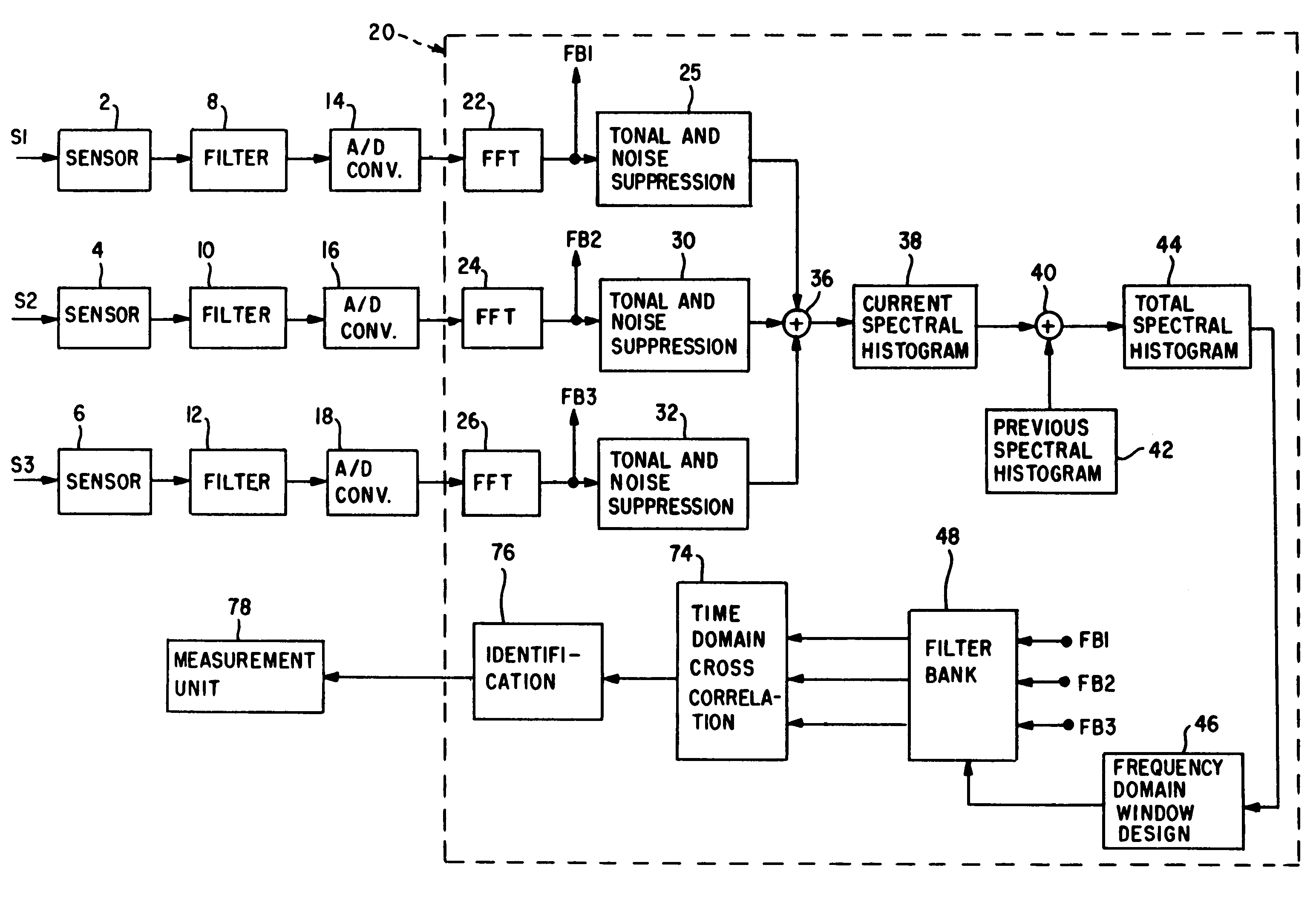
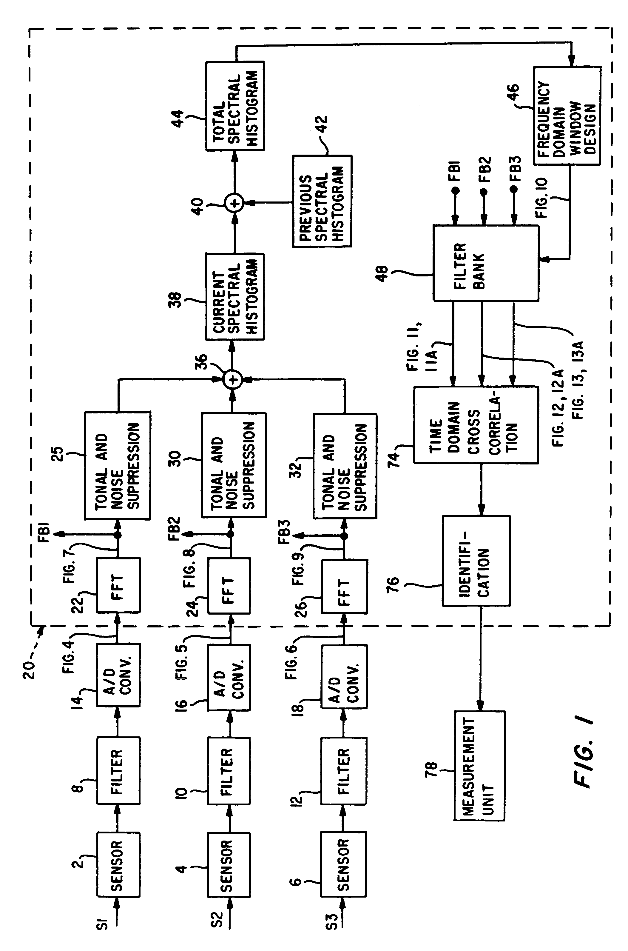
[0016]With reference to FIG. 1, a plurality of emitted acoustic signals, shown for purposes of illustration as three in number, are designated as S1, S2 and S3. Signals S1, S2 and S3 are short, transient pulse modulated signals emitted from a signal source such as, for example, an active sonar source. Signals S1, S2 and S3 are sensed by sensors 2, 4 and 6, respectively, which provide corresponding analog output acoustic signals.

[0017]The analog output acoustic signals from sensors 2, 4 and 6 are filtered by filters 8, 10 and 12, respectively. Filters 8, 10 and 12 are anti-aliasing low pass filters and provide band selected / limited output signals which are digitized by analog to digital (A / D) converters 14, 16 and 18, respectively. The digitized signals provided by A / D converters 14, 16 and 18 are graphically represented in FIGS. 4, 5 and 6, respectively. In this regard, reference is made to FIG. 4 which illustrates the self-noise, transient portion of the digitized signals. The digi...


PUM


Abstract

A plurality of sensors and a digital adaptive tuning filter bank are used in extracting a desired emitted signal embedded in a noisy environment. By monitoring noise statistics of the sensor signals, the digital adaptive tuning filter bank automatically adjusts its upper (to eliminate strong tonals) and lower (to eliminate background noise) thresholds to obtain a discovery frequency band. The filter bank is designed by examining the discovery band across the sensors and over a predefined period of time. The method described significantly reduces the possibilities of matching self-noise transients (unwanted signals) and thus minimizes the false alarm rate in emitted signal recognition.

Description

BACKGROUND OF THE INVENTION[0001]The detection and measurement of short, transient pulse modulated signals emitted from an acoustic signal source such as, for example, an active sonar source has been the subject of recent efforts in the array signal processing field. However, much of this effort has not addressed three important practical issues: (1) how low the signal to noise ratio is (less than −10 dB); (2) the existence of self-noise transient signals; and (3) the presence of strong tonals. Therefore, prior art signal models and detection methods have not performed satisfactorily when applied to detecting, for example, actual underwater acoustic signals.[0002]In an actual underwater environment, machinery installed on surface ships and submarines, for example, inevitably generates a variety of harmonic resonance signals. These signals are called tonals. Tonals detected by an acoustic receiver can be much stronger than the emitted signal. Due to various underwater biological effe...

Claims


Application Information

Patent Timeline
IPC IPC(8): H04B1/06
CPCG10L21/0208G10L2021/02166G10L21/0216
Inventor LO, PEI-HWA
Owner ALLIEDSIGNAL INC
Why Eureka
Try Eureka