Magnetic resonance tomography apparatus

a tomography apparatus and magnetic resonance technology, applied in the field of magnetic resonance tomography apparatus, can solve the problems of affecting the quality or sensitivity and the difficulty in emulating the corresponding cable feedthrough in the cryostat for the purpose of reading out signals, so as to reduce the inherent noise of the magnetic resonance receive antenna

Active Publication Date: 2017-08-15
SIEMENS HEALTHCARE GMBH
View PDF17 Cites 4 Cited by
  • Summary
  • Abstract
  • Description
  • Claims
  • Application Information

AI Technical Summary

Benefits of technology

[0007]In order to reduce the inherent noise of the magnetic resonance receive antennas that is dominant in remote body arrays, the remote body array may be arranged in a cryostat for cooling purposes.
[0012]The magnetic resonance signals of magnetic resonance receive antennas located in a cryostat are amplified by a parametric mixer, and the magnetic resonance signals are converted into a different frequency range. The parametric mixer is also arranged in the cryostat. Contactless readout of the signals is achieved in this way, so no feedthroughs are to be provided in the cryostat. The signal-to-noise ratio of the read-out signal is maintained as a result of the amplification by the low-noise parametric mixer. In one embodiment, the parametric mixer is positioned in the cryostat and consequently has a very small noise number. The parametric mixer is supplied with power via the energy of the contactlessly transmitted auxiliary signal by which the mixed signal is also generated.
[0013]In one embodiment, the magnetic resonance tomography apparatus operates at a Larmor frequency of 123.2 MHz with a main magnetic field having a field strength of 3 tesla. The magnetic resonance tomography apparatus may also operate at a magnetic resonance frequency of 63.6 MHz with a magnetic field strength of the main magnetic field of 1.5 tesla. Other embodiments of magnetic resonance tomography apparatuses may also be provided. In one embodiment, the auxiliary signal lies at a frequency greater than the magnetic resonance frequency. The greater the frequency, the smaller the antennas used for the contactless communication interface may be dimensioned. Accordingly, greater frequencies have the advantage that the communication interface between the receive circuit and the evaluation circuit may be embodied in compact form. Higher frequencies also result in a higher stable amplification of the parametric converter.
[0015]The parametric mixer assigned to the respective magnetic resonance receive antenna may include one or more varactor diodes for at least some of the magnetic resonance receive antennas. For example, the mixer may be embodied as a single-diode mixer, a two-diode mixer, or a four-diode mixer. The varactor diodes enable a nonlinear reactance, by which the signal amplification or signal conversion is achieved in a simple manner.
[0016]In a further embodiment, the contactless communication interface between the receive circuit and the evaluation circuit that are assigned to the respective magnetic resonance receive antenna is formed for at least some of the magnetic resonance receive antennas by a single integrated transmit and receive antenna in the receive circuit and a single integrated transmit and receive antenna in the evaluation circuit. Both the auxiliary signal directed to the receive circuit and the mixed signal directed to the evaluation circuit are transmitted via the two transmit and receive antennas. In this variant, a simple implementation of the contactless interface is achieved using just two antennas.

Problems solved by technology

A problem with magnetic resonance tomography apparatuses having remote body magnetic resonance receive antennas cooled by a cryostat is in the coupling-out of the signals, since embodying corresponding cable feedthroughs in the cryostat for the purpose of reading out the signals may be technically difficult.
This has the disadvantage that this will detrimentally affect the quality or sensitivity of the magnetic resonance receive antennas in the interior of the cryostat.

Method used


Image

  • Magnetic resonance tomography apparatus
  • Magnetic resonance tomography apparatus
  • Magnetic resonance tomography apparatus

Examples


Embodiment Construction

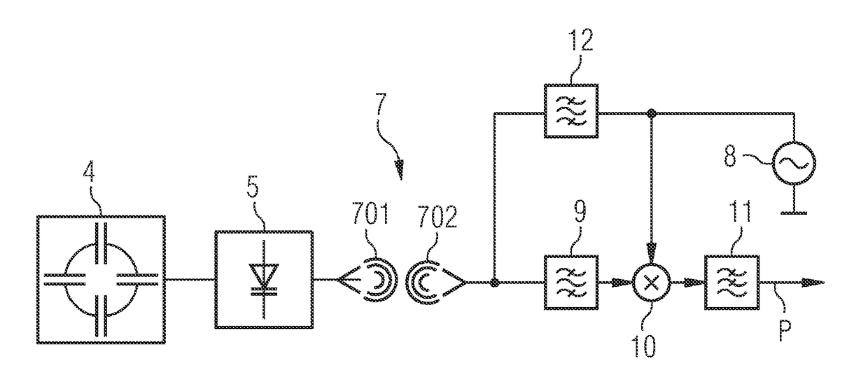
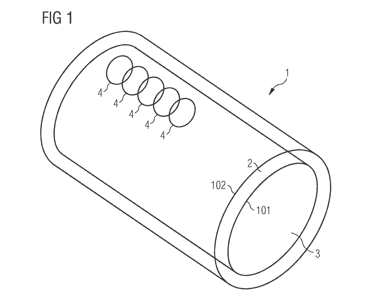
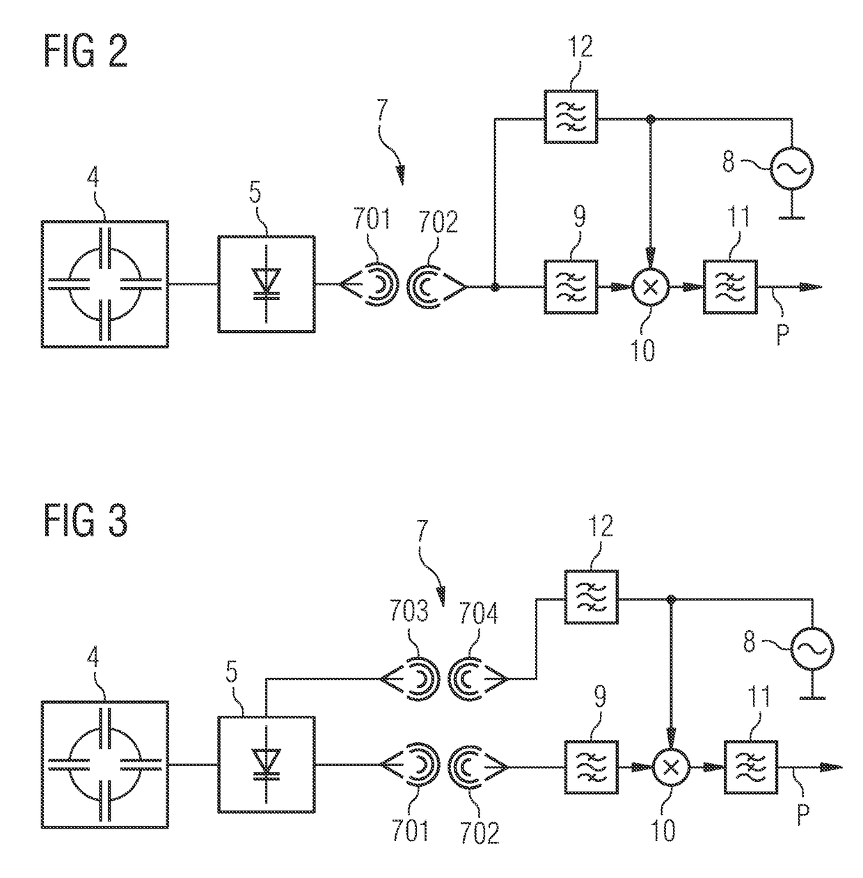
[0028]FIG. 1 shows a schematic view of a tube or tunnel 1 that is used in an embodiment of a magnetic resonance tomography apparatus for acquisition of magnetic resonance signals. The magnetic resonance tomography apparatus includes, in a known manner, further components that may be provided in the magnetic resonance tomography apparatus, such as, for example, a main magnet for generating the static main magnetic field. Only certain components of the system are explained below.

[0029]The tube forms a cylindrical housing having an inner face 101 and an outer face 102. The patient to be examined is introduced into an interior 3 of the cylinder. A plurality of magnetic resonance receive antennas 4 (indicated only schematically in the figure) are installed in the cylinder. Such antennas are provided essentially along the entire circumference of the cylinder. For clarity of illustration reasons, however, corresponding antennas are depicted in one partial area only. The antennas are embodi...


PUM


Abstract

A magnetic resonance tomography apparatus includes a receiving device having a number of magnetic resonance receive antennas for receiving a magnetic resonance signal in response to a radio frequency signal transmitted at a magnetic resonance frequency. A respective magnetic resonance receive antenna is connected to a parametric mixer. A receive circuit formed hereby is provided inside the cryostat and is coupled via a contactless communication interface to an evaluation circuit provided outside the cryostat. The evaluation circuit includes a local oscillator device for generating an auxiliary signal at an auxiliary frequency. The auxiliary signal is transmitted via the contactless communication interface to the receive circuit. The receive circuit is configured such that a mixed signal having a mixed frequency is generated via the parametric mixer from the auxiliary signal and the magnetic resonance signal and transmitted via the contactless communication interface to the evaluation circuit.

Description

[0001]This application claims the benefit of DE 10 2012 205 333.6, filed on Apr. 2, 2012, which is hereby incorporated by reference.BACKGROUND[0002]The present embodiments relate to a magnetic resonance tomography apparatus that is used for examining an object based on the principle of nuclear spin resonance.[0003]Magnetic resonance tomography apparatuses (e.g., nuclear spin tomography apparatuses) include imaging devices by which the spins of atomic nuclei are aligned and excited in order thereby to generate images of the tissue under investigation. A static background magnetic field is generated in a magnetic resonance tomography apparatus for that purpose. Radio frequency signals are transmitted at the known Larmor frequency that is dependent, for example, on the material under investigation and the magnetic field strength of the static background field. After the radio frequency signals are switched off, a magnetic resonance signal is received via corresponding magnetic resonanc...

Claims


Application Information

Patent Timeline
Patent Type & Authority Patents(United States)
IPC IPC(8): G01R33/34G01R33/36G01R33/3415
CPCG01R33/34G01R33/3692G01R33/3415G01R33/34015A61B5/055
Inventor MARTIUS, SEBASTIANVESTER, MARKUS
Owner SIEMENS HEALTHCARE GMBH
Why Eureka
Try Eureka