
Clock data recovery circuit

A technology of clock data recovery and clock recovery, which is applied in the direction of electrical components, digital transmission systems, transmission systems, etc., can solve the problems of large delay in the clock data recovery circuit system, low tolerance of frequency difference between the sending end and the receiving end, etc., and achieve reduction System delay, increased intrinsic noise, effects of high transfer rates

Active Publication Date: 2014-04-09
ETOWNIP MICROELECTRONICS BEIJING CO LTD
View PDF6 Cites 0 Cited by
  • Summary
  • Abstract
  • Description
  • Claims
  • Application Information

AI Technical Summary

Problems solved by technology

[0003] However, since the clock recovery module is implemented after the conversion module, the system delay of the entire clock data recovery circuit is relatively large, which affects the inherent noise of the transmitting end, jitter and noise in the data, non-ideal factors of the transmission path, and the transmission and receiving end. Relatively low tolerance for many adverse factors such as frequency differences

Method used


Image

  • Clock data recovery circuit
  • Clock data recovery circuit
  • Clock data recovery circuit

Examples


Embodiment Construction

[0018] In order to make the object, technical solution and advantages of the present invention clearer, the present invention will be further described in detail below in conjunction with the accompanying drawings. Obviously, the described embodiments are only some embodiments of the present invention, rather than all embodiments . Based on the embodiments of the present invention, all other embodiments obtained by persons of ordinary skill in the art without making creative efforts belong to the protection scope of the present invention.

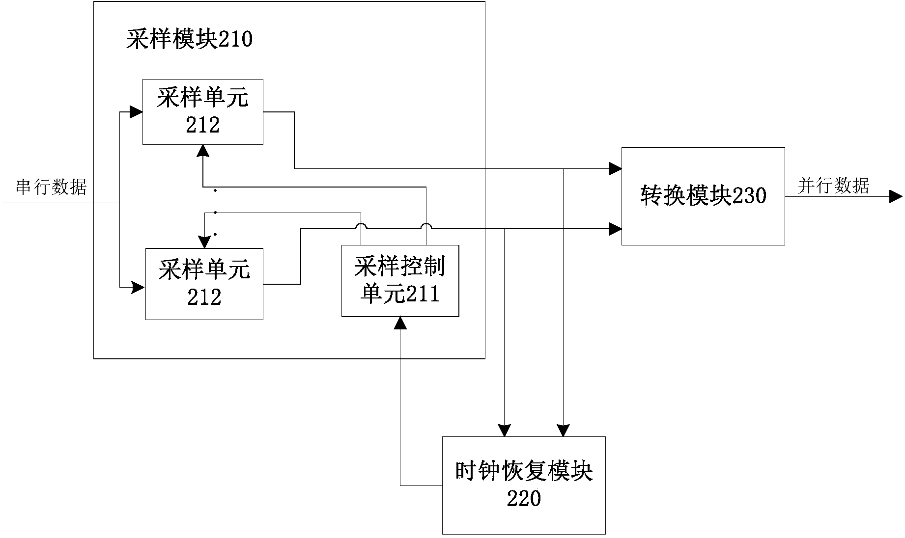
[0019] Below to figure 2 The clock data recovery circuit provided by the embodiment of the present invention will be described in detail as an example. like figure 2 As shown, it is a schematic structural diagram of a clock data recovery circuit provided by an embodiment of the present invention.

[0020] The clock data recovery circuit includes: a sampling module 210 , a clock recovery module 220 and a conversion module 230 .

[0021...


PUM


Abstract

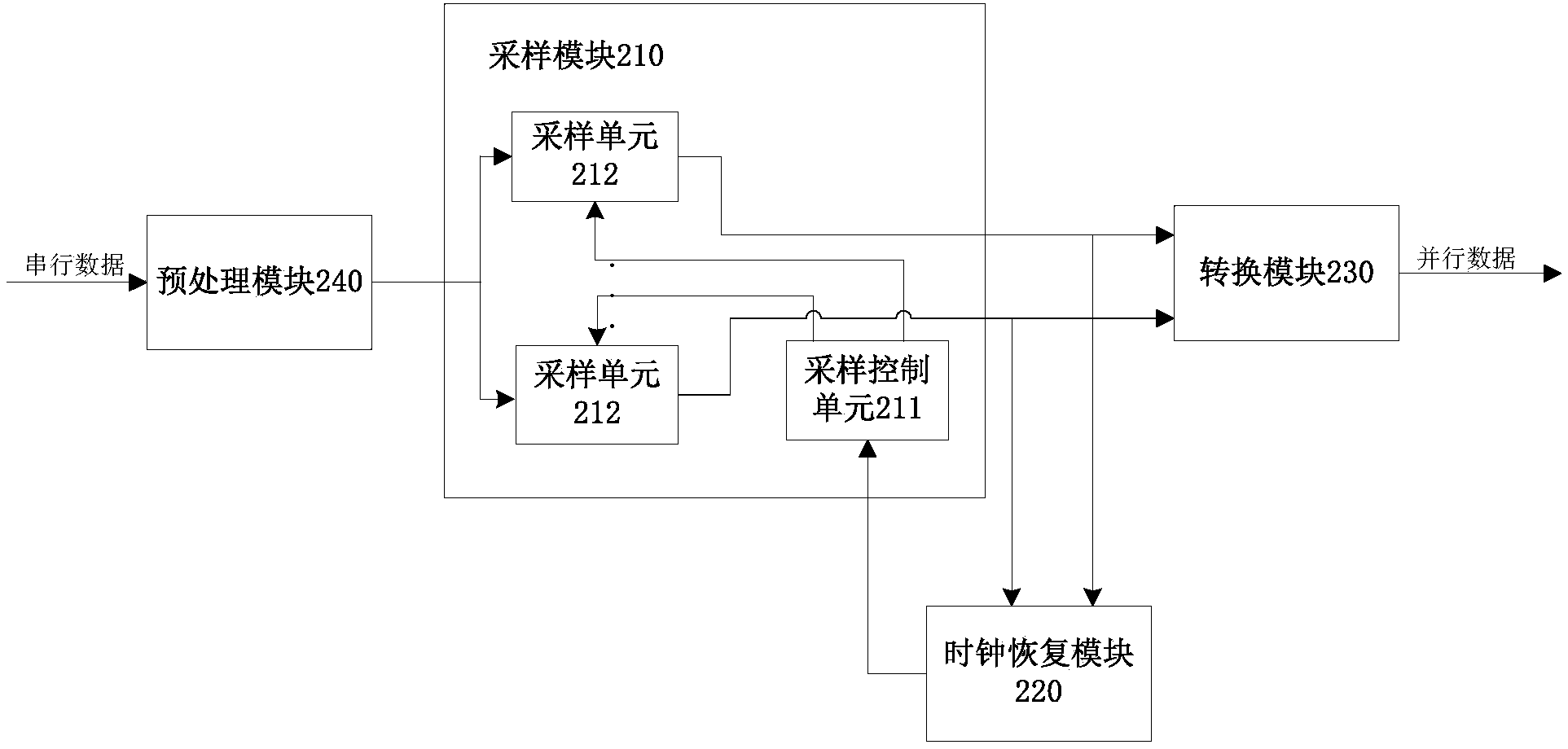
The invention relates to a clock data recovery circuit which comprises a sampling module and a clock recovery module. The sampling module comprises a sampling control unit and a plurality of sampling units. The sampling units are used for sampling serial data to obtain sampling data. The sampling control unit is used for controlling the sampling units to sample the serial data in sequence, and after all the serial data are sampled by the sampling units, the sampling units are controlled to simultaneously send the sampling data to the clock recovery module. The clock recovery module is used for recovering a clock according to the received sampling data.

Description

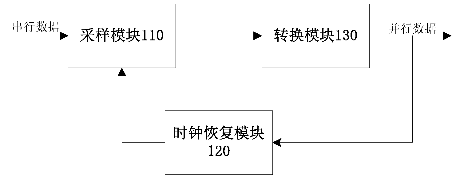
technical field [0001] The invention relates to a clock data recovery circuit. Background technique [0002] Currently, in serial communication systems, the clock data recovery circuit (CDR) plays a key role in the receiver. Clock recovery modules in clock data recovery circuits often work at extremely high rates. In implementation, in order to enable the clock data recovery circuit to achieve a high transmission rate, the clock data recovery module is usually placed after the conversion module for serial-to-parallel conversion. like figure 1 As shown, it is a schematic structural diagram of a clock data recovery circuit capable of achieving a high transmission rate in the prior art. The sampling module 110 sends the sampled serial data to the conversion module 130, and after the conversion module 130 serially converts the serial data with a high transmission rate into parallel, the data transmission rate will decrease accordingly, then the converted parallel data The op...

Claims


Application Information

Patent Timeline
Patent Type & Authority Applications(China)
IPC IPC(8): H04B1/16H04L7/00
Inventor 王军宁
Owner ETOWNIP MICROELECTRONICS BEIJING CO LTD
Learn More