
Eyeglasses with wireless communication features

Active Publication Date: 2006-03-14
OAKLEY INC
View PDF58 Cites 223 Cited by
  • Summary
  • Abstract
  • Description
  • Claims
  • Application Information

AI Technical Summary

Benefits of technology

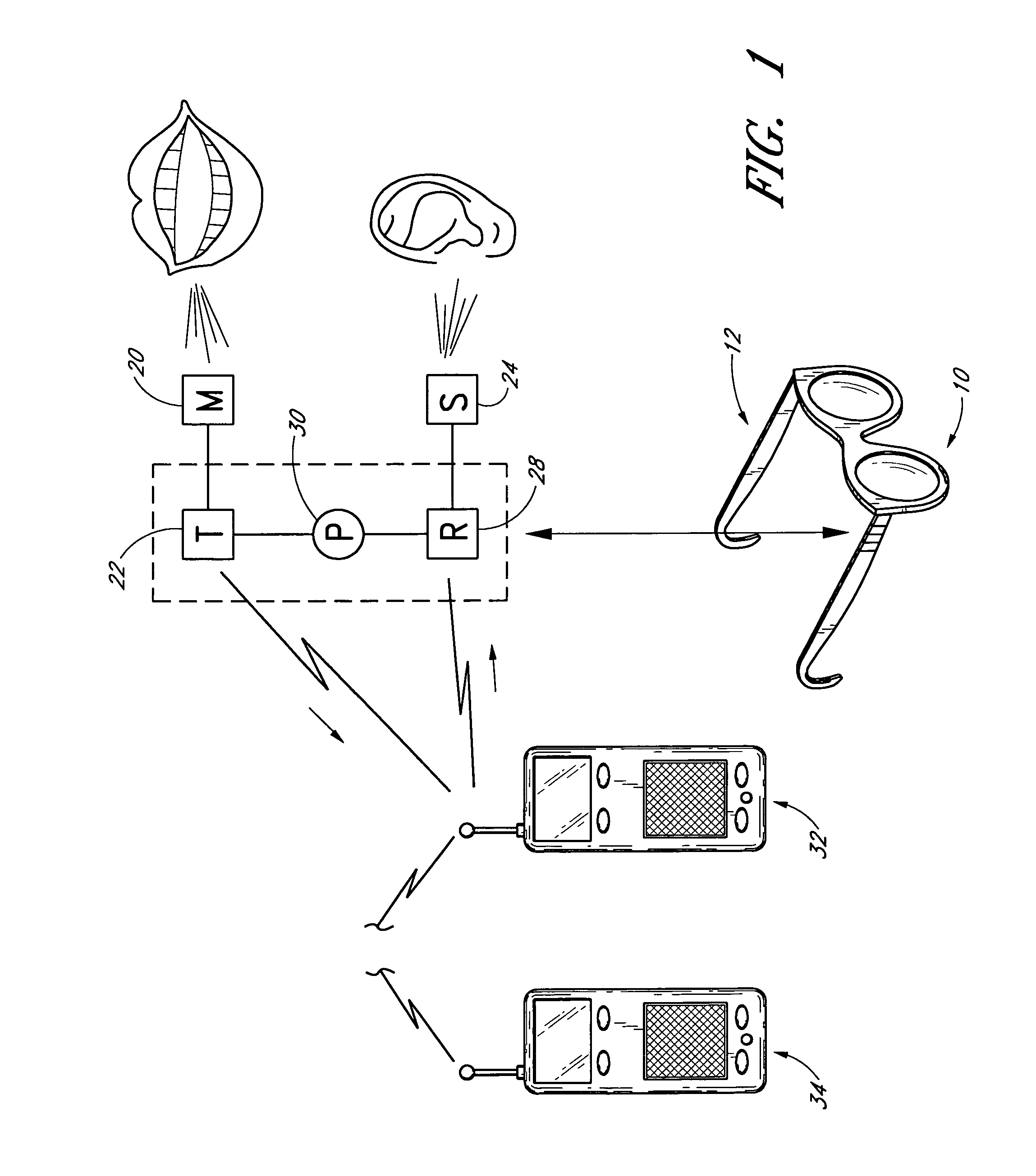
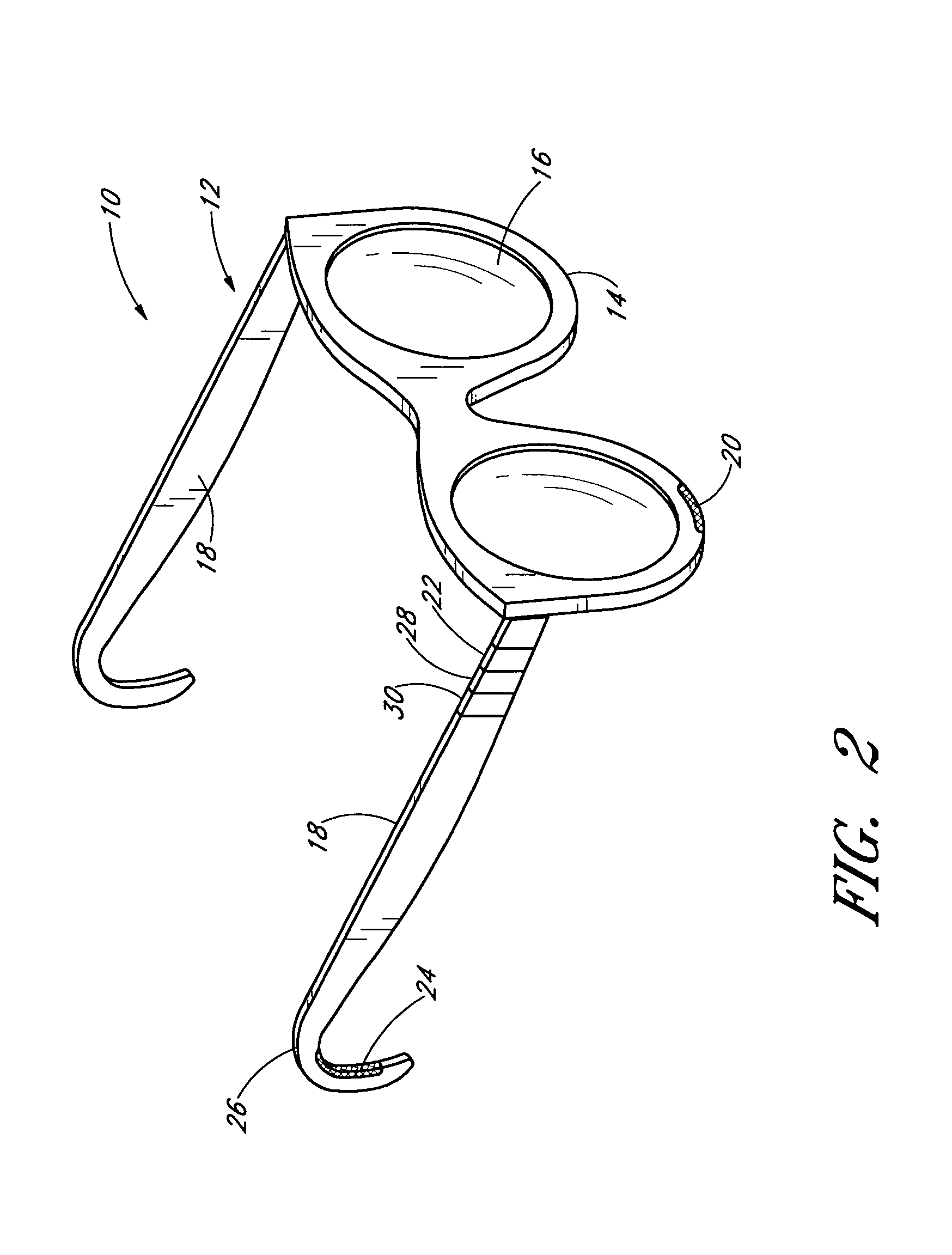
[0005]The present invention fulfills these and other needs by providing wearable communications devices for sending and receiving signals wirelessly to and from a remote cell phone or other electronic device. Generally described, the invention comprises an eyeglasses device having an eyeglasses frame and having a microphone, a transmitter, a speaker, a receiver, and a power source connected together and mounted to the frame. Whenever a user has on the eyeglasses, he can converse over the cell phone privately, easily, and in a hands-free manner. Particularly for people who wear prescription glasses, the invention provides a great convenience, as they will often or most always be wearing their glasses. Thus, users can have private, hand-free conversations on their cell phones, without having to put on a headset, and afterward remove, store, and carry the headset.
[0008]Additional alternative embodiments provide wearable communication devices with a clip-on member (instead of an eyeglasses frame) that mounts to a pair of conventional eyeglasses. Similar to the above embodiments, these have a microphone, a transmitter, a receiver, a speaker, and a power source, all mounted to the clip-on member. These embodiments permit retrofitting the wearable device onto a user's current glasses so that it is not necessary to go out a buy a new pair of glasses. Also, the user can easily change the wearable device from one pair of glasses to another.
[0010]Further alternative embodiments provide wearable communication devices with a frame in the form of a hat, headband, earmuffs, or another article that can be worn on a user's head. Similar to the above embodiments, these have a microphone, a transmitter, a receiver, a speaker, and a power source, all mounted to the frame. These embodiments provided similar benefits, for instance, a user can wear a hat and use the communications features to conveniently and privately communicate on his or her cell phone.

Problems solved by technology

A drawback to the use of cell phones, however, is that speaking on a cell phone can be a disturbance to bystanders.
Similarly, using PDA's, laptops, etc. with capabilities for voice recognition and / or accessing and playing music or other audio can be an annoyance to others.
Additionally, holding a cell phone to one's head while driving an automobile can be unsafe because the driver has only one hand available to operate the vehicle.
Furthermore, holding a cell phone can be difficult or at least a distraction in many other situations, such as while typing on a keyboard, walking down a street or in a mall with one's hands full, while riding a bike, and so forth.
However, such headsets are typically donned and removed each time the cell phone is used, which can be a significant inconvenience.
Also, such headsets must be stored somewhere when they are removed and not in use, making it more likely that the user will forget them, break them, or be further inconvenienced by carrying a case for them.

Method used


Image

  • Eyeglasses with wireless communication features
  • Eyeglasses with wireless communication features
  • Eyeglasses with wireless communication features

Examples


embodiment 410

[0037]FIG. 6 shows a fourth alternative embodiment 410 of the present invention, with the speaker 424 attached to a pivotal extension arm 442 that is pivotally connected to one of the support arms 418. Of course, the extension arm can be telescopic, generally rigid, or generally flexible, as may be desired. In this alternative embodiment, the speaker 424 can be extended, pivoted, or otherwise moved into a first position when needed for use, and retracted, pivoted, or otherwise moved to a second non-obtrusive position when not needed.

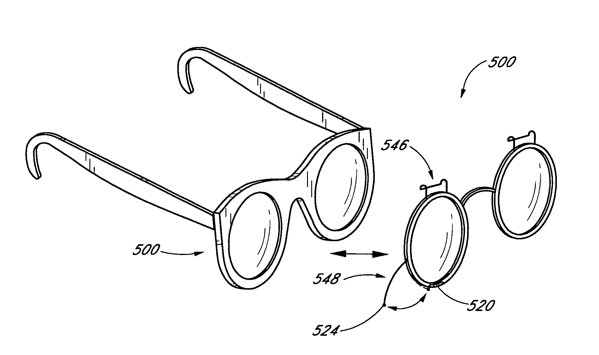
[0038]FIGS. 7–9 show additional alternative embodiments of the present invention. In these embodiments, instead of the communication components being mounted directly to the eyeglasses, there is provided an attachment member having at least one connector that permits removably mounting the member onto a conventional eyeglasses frame. The connector is provided by a clip, though another mounting structure can be used as desired, such as a hook, snap, screw...

embodiment 510

[0039]For example, FIG. 7 shows a fifth alternative embodiment 510 with the attachment member provided by a conventional clip-on lens holder 544 and the connector provided by two (or another number) of clips 546 for mounting onto the lens holder of a conventional eyeglasses frame 500. The microphone 520 and the speaker 524 are mounted to the lens holder 544. The speaker 524 is connected to the lens holder 544 by a pivotal extension arm 548 or by another extension arm, and the microphone can be embedded or otherwise attached to the clip-on lens holder.

embodiment 610

[0040]FIG. 8 shows a sixth alternative embodiment 610 with the attachment member provided by a frame 650 and the connector provided by a clip 651 formed by a bent section of the frame 650, for mounting onto one of the support arms of a conventional eyeglasses frame 600. The microphone 620 and the speaker 624 are attached to the clip frame 650, with the microphone 620 attached by a pivotal and / or telescopic extension arm 652 or other extension arm, and the speaker 624 attached by a pivotal extension arm 654 or other extension arm.


PUM


Abstract

A microphone, transmitter, speaker, receiver, and power source, all mounted to an eyeglasses frame, for sending and receiving signals wirelessly to and from a remote cell phone or other electronic device. The microphone and the transmitter can be mounted to extension arms that can be extended, pivoted, or otherwise moved to a position for use, and then moved to a stored position when not in use. Alternatively, the microphone, transmitter, speaker, receiver, and power source, can be mounted onto a clip-on or other attachment member that mounts onto a conventional eyeglasses frame, or to a hat or other article worn on the head.

Description

TECHNICAL FIELD[0001]This invention relates to wearable audio communication devices and, more particularly, to eyeglasses with wireless audio communication features for remote use of a cell phone or other electronic device.BACKGROUND OF THE INVENTION[0002]Technological advances in the telecommunications and computer-related industries have provided cell phones, web phones, personal digital assistants (PDA's), hand held computers, lap tops, and other portable devices that allow for instant communication and access to information. These portable devices provide the benefit of allowing people to be connected wherever they are. A drawback to the use of cell phones, however, is that speaking on a cell phone can be a disturbance to bystanders. This is especially the case in public and other places where others generally do not want to be disturbed, such as restaurants, theaters, churches, and so forth. Similarly, using PDA's, laptops, etc. with capabilities for voice recognition and / or ac...

Claims


Application Information

Patent Timeline
IPC IPC(8): H04M1/00G02C11/06H04B1/38H04M1/05H04M1/60H04M1/72412
CPCA42B1/245G02C11/06H04B1/385G02C11/10H04M1/05H04M1/6066H04M2250/02H04B2001/3866H04M1/72412A41D1/002A41D20/00
Inventor WARREN, PETER
Owner OAKLEY INC
Learn More