Method for the operation of a hearing aid device or hearing device system as well as hearing aid device or hearing device system

a technology of hearing aids and hearing aids, applied in the direction of public address systems, electrical equipment, transmission, etc., can solve the problems of loop amplification, no longer achievable hearing aid gain, and extremely unpleasant for hearing aid users, so as to reduce feedback-conditioned oscillations and without noticeably deteriorating sound quality

Active Publication Date: 2006-03-14
SIVANTOS PTE LTD
View PDF22 Cites 26 Cited by
  • Summary
  • Abstract
  • Description
  • Claims
  • Application Information

AI Technical Summary

Benefits of technology

[0016]An object of the present invention is to provide a method for operating a hearing aid device or hearing device system as well as a hearing aid device or hearing device system that avoids feedback-conditioned oscillations without noticeably deteriorating the sound quality.
[0017]This object is inventively achieved by a method for operating a hearing aid device or hearing device system, comprising generating a

Problems solved by technology

This feedback is expressed in pronounced feedback-caused oscillations having a specific frequency, called “whistling”, that is usually extremely unpleasant both for the hearing aid user and as well as for people in the immediate surroundings.
The critical disadvantage of this approach, however, is that the hearing aid gain required given more pronounced hearing impairment can no longer be achieved as a result of this limitation.
Since the loop amplification, however, can constantly change during daily life, the benefit is likewise limited.
However, these compensation methods assume uncorrelated, i.e., ideally, “white”, input signals.
Tonal input signals that always exhibit a high time correlation lead to an incorrect estimate of the feedback path, which can lead to the fact that the tonal input signal itself is erroneously subtracted.
This is disadvantageous because the oscillation detectors can fundamentally not distinguish between tonal input signals and feedback whistling.
The result is that tonal input signals are interpreted as feedback oscillations and are then incorrectly reduced in level due to the reduction mechanism (for example, notch filters).
Due to echo effects and irritations as a result of desynchronized visual and auditive information, however

Method used


Image

  • Method for the operation of a hearing aid device or hearing device system as well as hearing aid device or hearing device system
  • Method for the operation of a hearing aid device or hearing device system as well as hearing aid device or hearing device system
  • Method for the operation of a hearing aid device or hearing device system as well as hearing aid device or hearing device system

Examples


Embodiment Construction

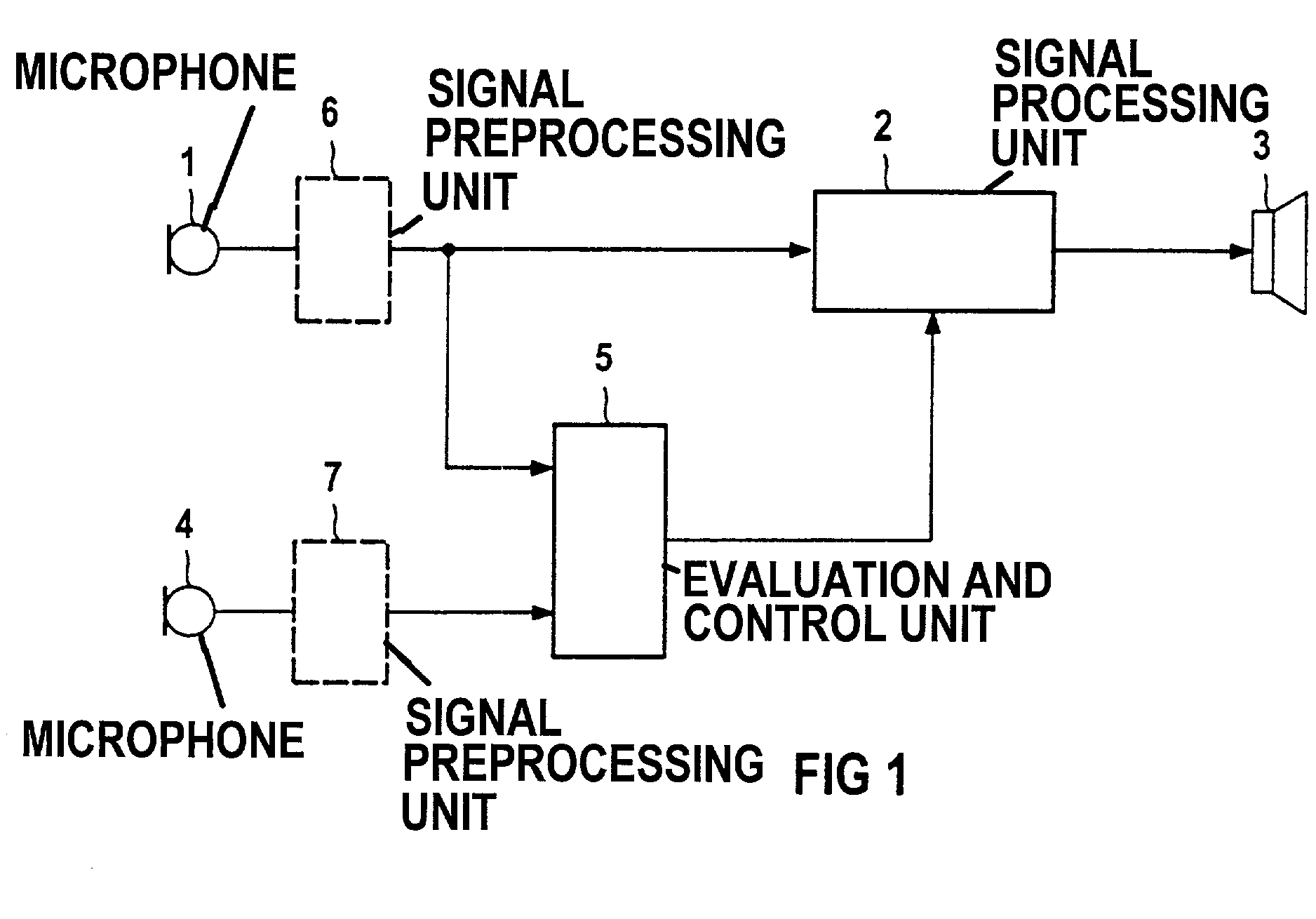
[0032]The hearing aid device schematically shown in FIG. 1 comprises a microphone 1, a signal processing unit 2 as well as an earphone 3. When sound from the earphone 3 proceeds back to the microphone 1, then feedback-conditioned oscillations (feedback) can arise. The conditions for this are that the “loop amplification” of the system, i.e., the product of the hearing aid gain and the attenuation of the feedback path, is greater than 1, and that the phase shift of this loop amplification corresponds to a whole-numbered multiple of 360°. Given the hearing aid device according to FIG. 1, a further microphone signal from a microphone 4 is supplied to an evaluation and control unit 5 in addition to the microphone signal of the microphone 1. The two microphones 1 and 4 are arranged such that useful sound is picked up approximately uniformly by both microphones. Sound proceeding from the earphone 3, however, cannot proceed to the microphone 4 or can at most proceed to it in a highly atten...


PUM


Abstract

For reducing feedback-conditioned oscillations in a hearing aid device, microphone signals of a first microphone and of a distanced, second microphone are compared to one another. When oscillations are detected at the same frequency in both microphone signals, these oscillations are determined to be useful (non-feedback) tonal signals. Oscillations that are only present in one of the microphone signals, in contrast, are feedback-conditioned and are suppressed using suitable measures.

Description

BACKGROUND OF THE INVENTION[0001]1. Field of the Invention[0002]The invention is directed to a method for operating a hearing aid device or hearing device system having at least one first microphone for generating a first microphone signal and a second microphone distanced from the first for generating a second microphone signal. The invention is also directed to a hearing aid device or hearing device system for implementing the method.[0003]2. Description of the Related Art[0004]Acoustic feedback frequently occurs in hearing aid devices, particularly for hearing aid devices having a high gain. This feedback is expressed in pronounced feedback-caused oscillations having a specific frequency, called “whistling”, that is usually extremely unpleasant both for the hearing aid user and as well as for people in the immediate surroundings.[0005]Feedback can occur when sound that is picked up via the microphone of the hearing aid device is amplified by a signal amplifier and output via the ...

Claims


Application Information

Patent Timeline
IPC IPC(8): H04R25/00H04B15/00
CPCH04R25/407H04R25/552H04R25/453
Inventor HOHMANN, VOLKERHAMACHER, VOLKMARHOLUBE, INGAKOLLMEIER, BIRGERWITTKOP, THOMAS
Owner SIVANTOS PTE LTD
Why Eureka
Try Eureka