
Equipment and method for changing a blade

a technology for changing equipment and blades, which is applied in the direction of vehicle maintenance, vehicle cleaning, manufacturing tools, etc., can solve the problems of difficult feeding the band through the described changing equipment, time-consuming and labor-intensive, and the state of the art is avoided, and achieves precise control of the blade. , the effect of simple and reliabl

Inactive Publication Date: 2006-03-21
VALMET TECH INC
View PDF8 Cites 4 Cited by
  • Summary
  • Abstract
  • Description
  • Claims
  • Application Information

AI Technical Summary

Benefits of technology

[0010]The invention is intended to create a new type of equipment, which is simpler and more reliable than previously and by means of which the drawbacks of the state of the art are avoided. The invention is also intended to create a new type of method for changing a blade, which can be applied simply in the various positions that utilize a blade. The use of the equipment according to the invention gives precise control over the blade, without creating peaks of stress that are detrimental to the blade. This is achieved with the aid of simple guide members, which are arranged to operate in stages. At the same time, the equipment is not only versatile, but also clear and reliable in operation. The equipment can be applied in different positions and with different kinds of blade. In the method according to the invention, the blade's natural properties are exploited, permitting the blade to be guided and fed rapidly and safely. The invention also allows a faster blade change than before to be achieved, as the entire production process is controlled in a new manner.

Problems solved by technology

However, changing long blades is difficult and can even be dangerous.
In addition, changing a blade is time consuming.
However, feeding the band by means of the changing equipment described is often difficult, because in reality there is generally little space around the doctor apparatus.
This makes the changing equipment less reliable and increases the purchase and operating costs of the changing equipment.

Method used


Image

  • Equipment and method for changing a blade
  • Equipment and method for changing a blade
  • Equipment and method for changing a blade

Examples


Embodiment Construction

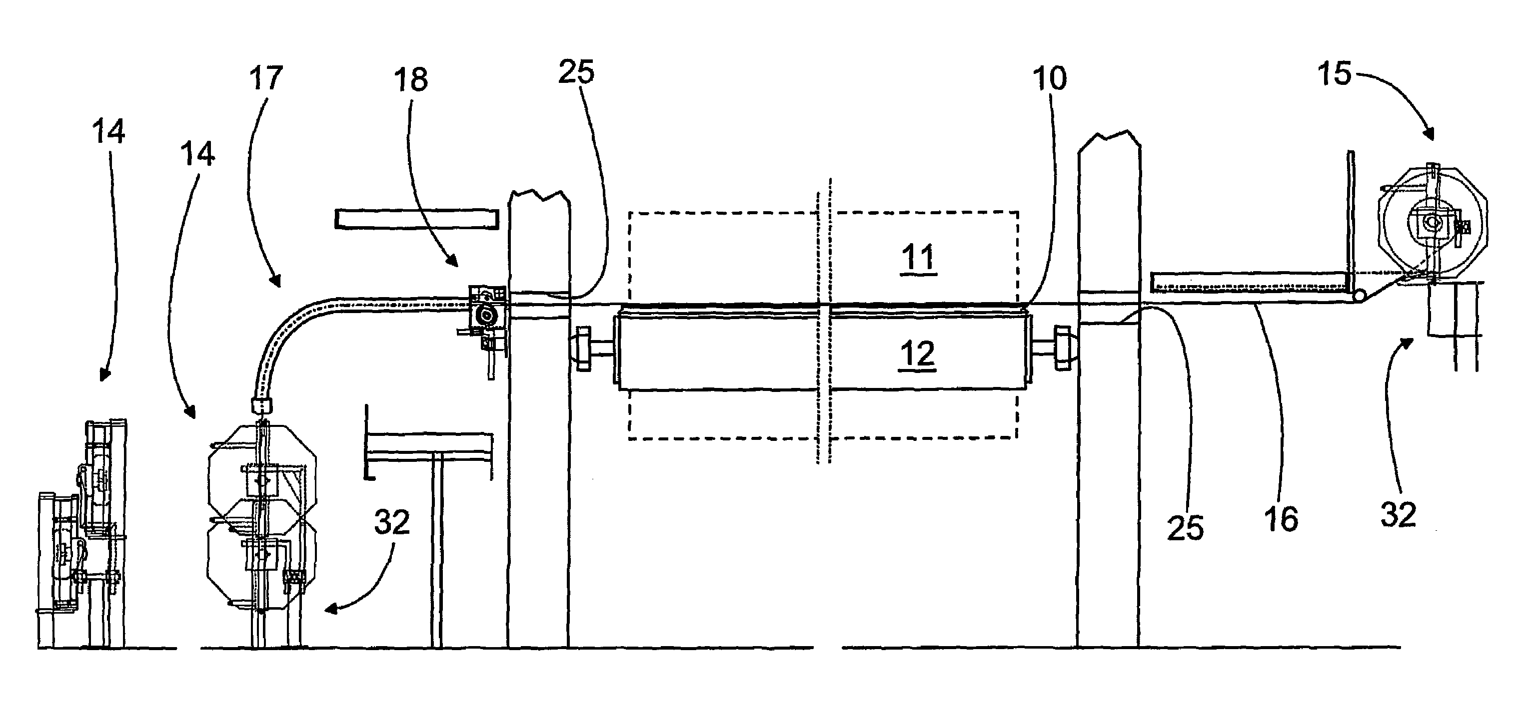
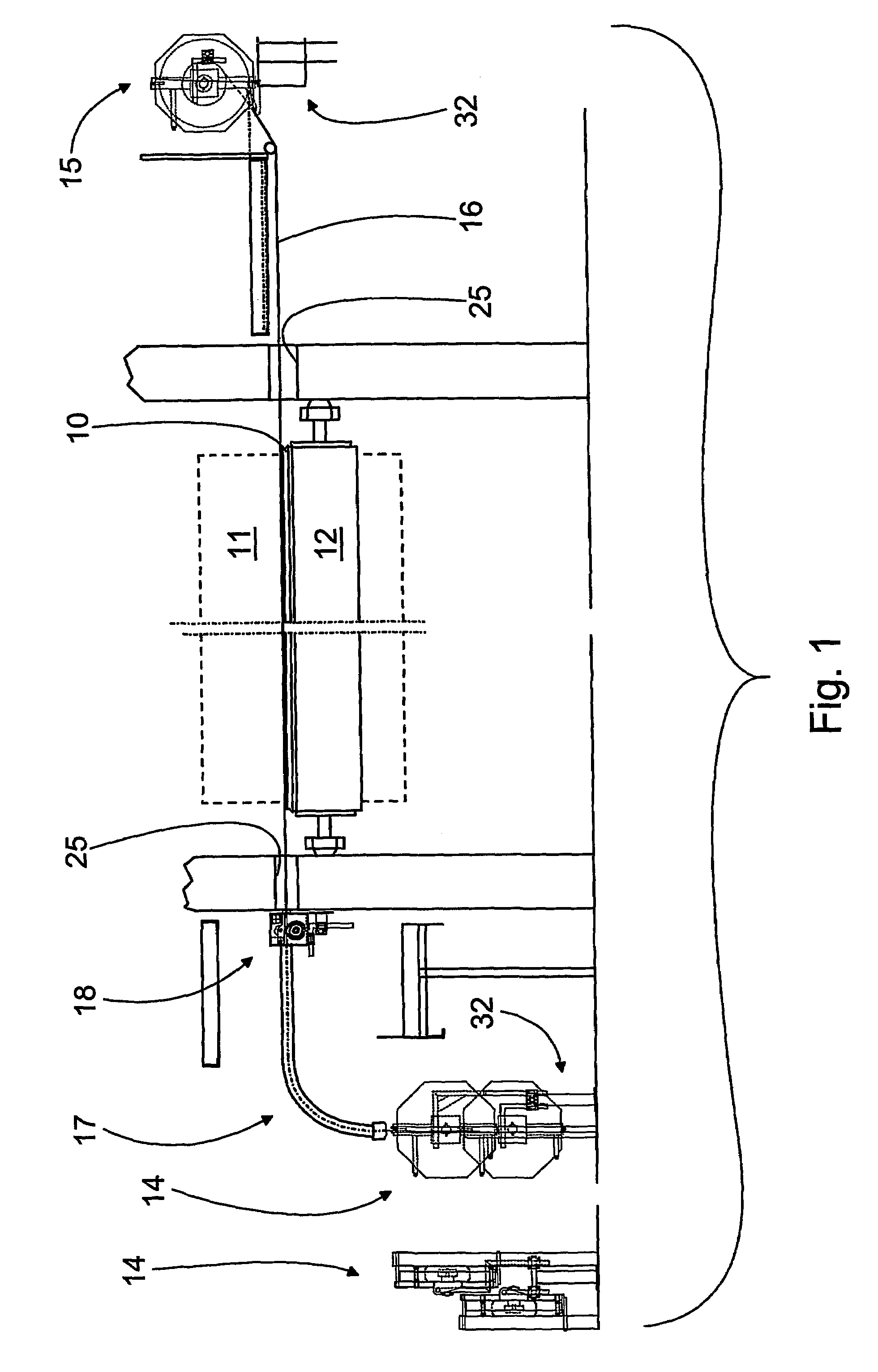
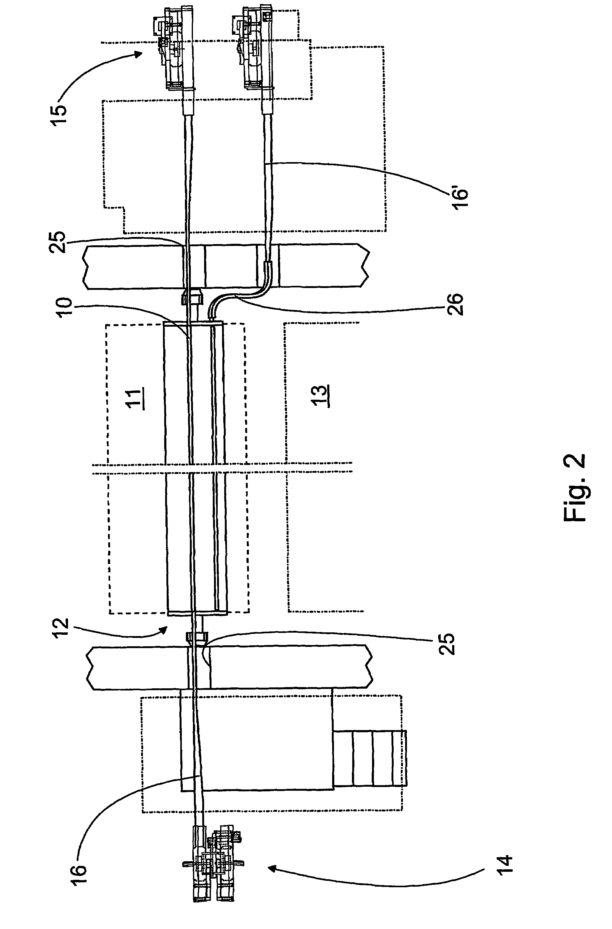
[0017]FIG. 1 shows the equipment according to the invention for changing a blade. In general, the blade is intended to be used in a blade holder 10, in connection with doctoring or coating. FIG. 1 shows the equipment installed in connection with the double doctor 12 of the center roll 11 of the press section of a paper machine. FIG. 2 also shows part of a drying cylinder 13 and the center roll 11 depicted by a broken line. In practice, there is a separate apparatus for each band, the operation of each of which can be controlled independently. In addition to blades intended for doctoring, the equipment can also be used to change, for example, coating and creping blades, depending on the position. To make blade changing faster, use is made of bands formed of one or several blades, which are, as such, known. The material of the band-like blades can also vary in different applications.

[0018]In order to change the flexible band-like blade, the equipment of the blade holder 10 includes tw...


PUM

PropertyMeasurementUnit
distanceaaaaaaaaaa
flexibleaaaaaaaaaa
distanceaaaaaaaaaa

Abstract

Equipment and a method for changing a blade which is intended to be placed in a blade holder (10) and which is preferably arranged as a flexible band (16). The equipment has reels (14, 15) for keeping the band (16) reeled and transfer devices (18) for moving the band (16) in the blade holder (10) between the reels (14, 15). The equipment includes guide devices (17) for guiding the band (16) from a reel (14, 15) to the blade holder (10) and vice versa. The guide devices (17) are arranged to turn the band (16) longitudinally to be essentially parallel to the blade holder (10). The closest guide member (20) of the guide members (20, 20′) belonging to the guide devices (17) is rotated to a position that essentially corresponds to the position of the blade holder (10) turned to the blade-changing position.

Description

CROSS REFERENCES TO RELATED APPLICATIONS[0001]This application is a National Stage Application of International Application PCT / FI02 / 00477, filed Jun. 4, 2002, and claims priority on Finnish Application No. 20015006, Filed Jun. 5, 2001.STATEMENT AS TO RIGHTS TO INVENTIONS MADE UNDER FEDERALLY SPONSORED RESEARCH AND DEVELOPMENT[0002]Not applicable.BACKGROUND OF THE INVENTION[0003]The present invention relates to equipment for changing a blade, which blade is intended for use in connection with doctoring or coating, and which is preferably arranged as a flexible band with one or several blades, the equipment including[0004]a first reel in connection with one end of the blade holder for storing the unused band reeled,[0005]a second reel in connection with the other end of the blade holder for storing the used band reeled,[0006]transfer devices for moving the band in the blade holder between the reels, and[0007]guide devices for guiding the band from the reel to the blade holder and / or ...

Claims


Application Information

Patent Timeline
Patent Type & Authority Patents(United States)
IPC IPC(8): B21B45/02B31F1/14D21G3/00B05C11/02D21H23/34D21H25/10
CPCB05C11/026D21H25/10D21G3/005
Inventor ESKELINEN, ILKKANARHI, ARIRUOTSALAINEN, HARRI
Owner VALMET TECH INC
Features
  • Generate Ideas
  • Intellectual Property
  • Life Sciences
  • Materials
  • Tech Scout
  • Unparalleled Data Quality
  • Higher Quality Content
  • 60% Fewer Hallucinations
Learn More