Brake actuator comprising an energy accumulator and an inertia weight

a technology of inertia weight and energy accumulator, which is applied in the direction of braking system, mechanical equipment, transportation and packaging, etc., can solve the problems of premature wear or damage, and achieve the effects of reducing the shock load acting on the braking system, reducing construction costs, and reducing load

Inactive Publication Date: 2006-03-21
KNORR BREMSE SYST FUR SCHIENENFAHRZEUGE GMBH
View PDF7 Cites 15 Cited by
  • Summary
  • Abstract
  • Description
  • Claims
  • Application Information

AI Technical Summary

Benefits of technology

[0005]In view of the above, the present invention is based on a brake actuator which, when the accumulator-type brake unit is triggered, lower loads will occur, while the braking effect is simultaneously high. Furthermore, this object is to be connected with lower constructional costs and should be able to be implemented in a space-saving manner.
[0006]Because the potential energy abruptly released when the accumulator-type brake is triggered is, for the most part, converted to rotational energy of the inertia weight, the remaining kinetic energy, by means which the elements of the power converter can be accelerated in the brake application direction, is reduced. For this reason, the shock load acting upon the braking system is reduced, whereby its service life and reliability is increased. The inertia weight is provided in addition to possibly already existing rotational bodies used exclusively for locking the accumulator-type brake unit. The rotational bodies also rotate after the release of the locking device. In particular, the inertia weight has a mass moment of inertia which is sufficient for a noticeable damping of the release of energy abruptly occurring during the release of the locking device. In comparison to linearly moving inertia weights, which require a relatively long acceleration path for generating a significant energy dissipation, less space is required for rotatory inertia weights. In addition, in contrast to oil-pressure-type or gas-pressure-type shock absorbers, the rotational inertia weight can be used independent of the temperature.
[0007]According to a particularly preferred arrangement, the forces and / or torques generated by the energy accumulator, when the locking device is locked, can be introduced at least by a portion of the inertia weight into a housing of the brake actuator and can be supported there. As a result, the inertia weight forms a component of the locking device and is integrated into its flux of force. The inertia weight therefore has a double function in that, in addition to reducing excess energy, it simultaneously acts as a locking element, whereby a particularly space-saving and light construction is obtained.
[0008]According to a further development, a transmission gearing with a preferably large gear ratio is arranged between the energy accumulator and the inertia weight. As a result, the forces are reduced which have to be applied for locking the inertia weight, which is simultaneously used as a locking element, in the release position. When the inertia weight is locked, for example, by electromagnetic holding forces, solenoid coils of a lower magnetic force are sufficient, whereby the current consumption and the heating-up of the brake actuator are reduced. Simultaneously, because of the large ratio, the rotational speed of the inertia weight is increased which is entered in a squared manner into the rotational energy, so that a high degree of damping will exist when the accumulator-type brake unit is triggered.
[0009]The inertia weight is expediently releasably coupled with the energy accumulator by a slipping clutch which is designed such that, after the braking position has been reached, the inertia weight is uncoupled from the energy accumulator. If the inertia weight and the bearing frictions are designed such that the inertia weight continues to rotate after the braking position has been reached, as a result of this arrangement, a gradual reduction of the rotational energy stored in it can take place, which has a positive effect on the service life of the brake actuator.

Problems solved by technology

In this case, the braking system is subjected to high forces which may result in premature wear or damage.

Method used


Image

  • Brake actuator comprising an energy accumulator and an inertia weight
  • Brake actuator comprising an energy accumulator and an inertia weight
  • Brake actuator comprising an energy accumulator and an inertia weight

Examples


Embodiment Construction

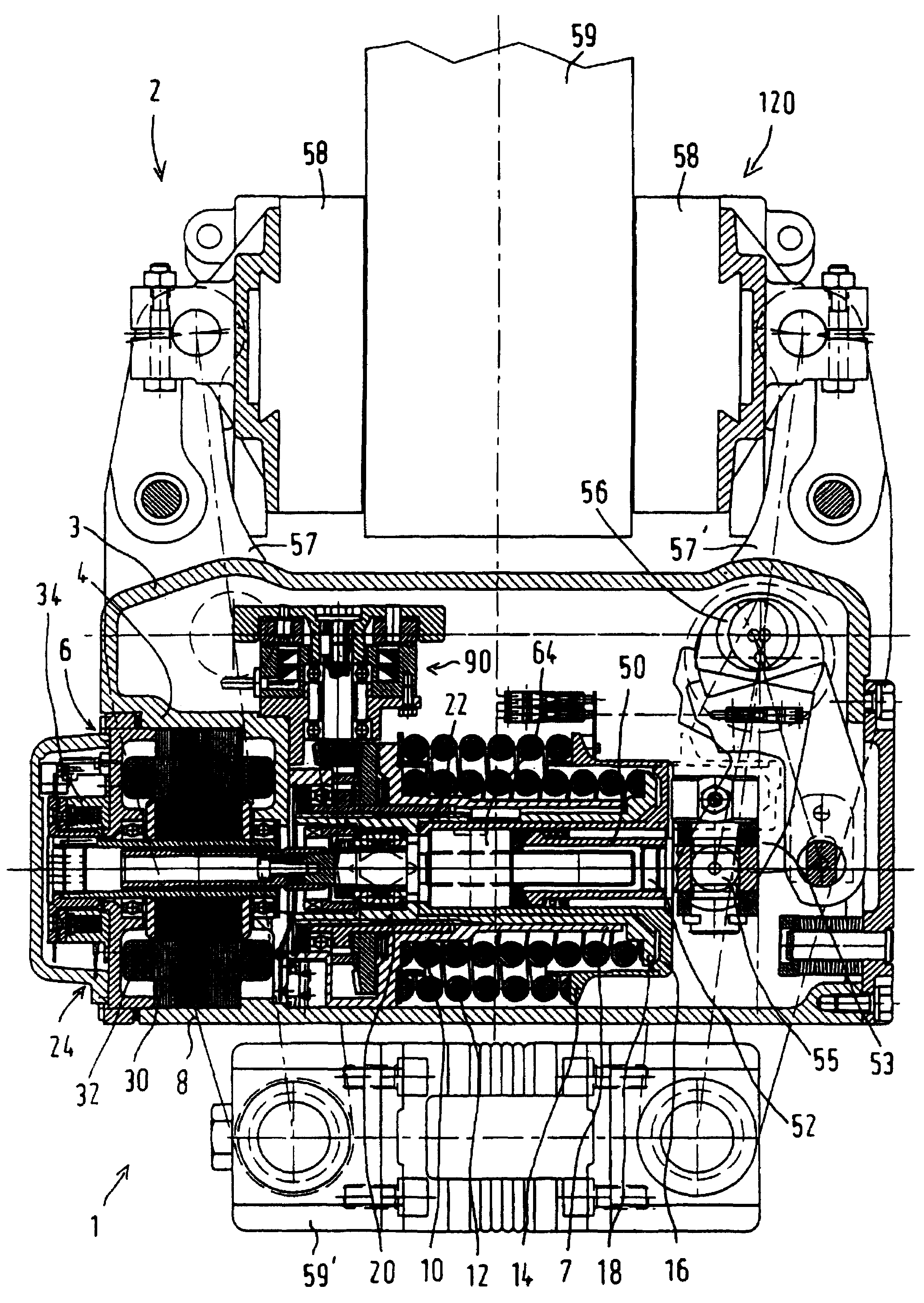
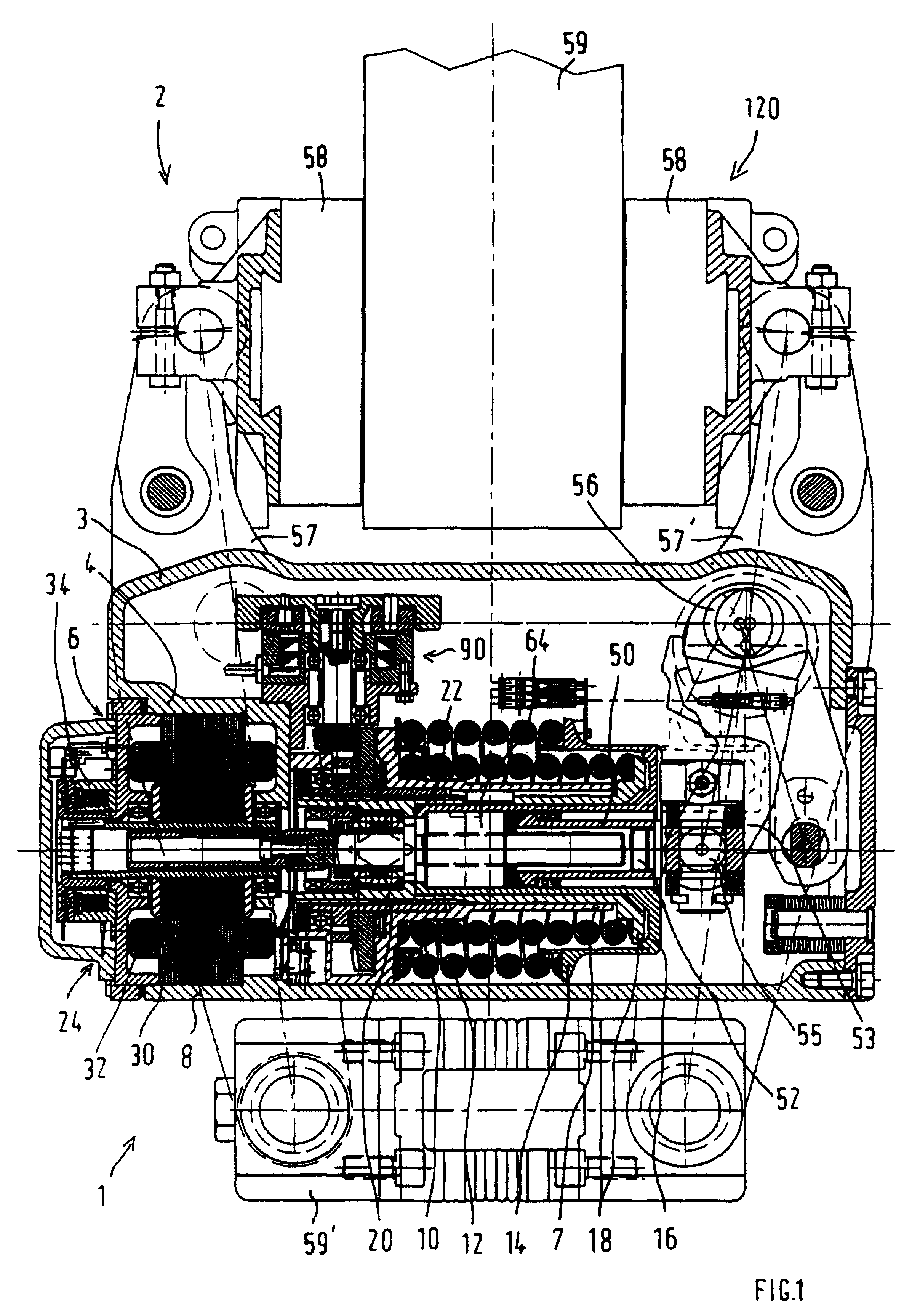
[0013]The preferred embodiment of a brake actuator, which as a whole has the reference Number 1 in FIG. 1 and is illustrated in a release position, is used as the driving unit of an electromechanical brake application device 2 of a rail vehicle. The brake actuator 1 has an essentially hollow-cylindrical actuator housing 3 which is closed off by a lid section 4 toward an axial end. The lid section 4 has an end-side opening 6. Starting from the lid section 4, the actuator housing 3 has an essentially double-walled construction. In the space between an interior wall 7 and an exterior wall 8, an interior accumulator-type spring 10 and an exterior accumulator-type spring 12 coaxial thereto being arranged. The exterior accumulator-type spring 12 encloses the interior accumulator-type spring 10.

[0014]The accumulator-type springs 10, 12 are preferably constructed as coil springs and are in each case supported by their one end on the actuator housing 3. The exterior accumulator-type spring 1...


PUM


Abstract

The invention relates to a brake actuator, especially for a rail vehicle brake, comprising an accumulation brake unit having an energy accumulator for storing and supplying energy for applying the brake, preferably in the event of safety braking and / or park braking, and a locking device for locking and unlocking the energy accumulator. After the release of the locking device, an inertia weight from part of the energy released from the energy accumulator can be subjected to a rotational movement for damping purposes.

Description

BACKGROUND AND SUMMARY OF THE INVENTION[0001]The invention relates to a brake actuator, particularly for a rail vehicle brake.[0002]Currently, three types of wheel braking systems are essentially used in the rail vehicle field: Pneumatic or electro-pneumatic braking systems, hydraulic or electro-hydraulic braking systems as well as mechanical or electromechanical braking systems. The wheel braking system may be constructed as an active or passive braking system, depending on whether the power of the brake actuator has to be applied for the engaging (active braking system) or for the releasing of the brake (passive braking system). In case of operating disturbances, energy is stored in air brake reservoirs if pneumatic systems are used; energy is stored in hydraulic reservoirs if hydraulic systems are used; and energy is accumulated in the form of accumulator-type springs when electromechanical systems are used.[0003]From the prior art, electromechanical rail vehicle brakes are known...

Claims


Application Information

Patent Timeline
Patent Type & Authority Patents(United States)
IPC IPC(8): B60T13/04B60T8/72B60T13/74B61H5/00F16D55/224F16D65/14F16D65/16F16F15/30
CPCB60T13/743B61H5/00F16D55/2245F16D2121/24F16D2121/26F16D2125/32F16D2129/08F16D2125/52F16D2125/582F16D2125/585F16D2127/008F16D2127/06F16D2129/046F16D2125/40
Inventor KRUG, RITAFRIESEN, ULFSTALTMEIR, JOSEF
Owner KNORR BREMSE SYST FUR SCHIENENFAHRZEUGE GMBH
Why Eureka
Try Eureka