
Process and assembly for identifying and tracking assets

Inactive Publication Date: 2006-03-21
WEATHERFORD TECH HLDG LLC
View PDF70 Cites 115 Cited by
  • Summary
  • Abstract
  • Description
  • Claims
  • Application Information

AI Technical Summary

Benefits of technology

[0011]In yet another characterization of the present invention, an assembly is provided for use as a fluid conduit. The assembly comprises a tubular, a collar releasably secured to one end

Problems solved by technology

However, problems routinely occur with this procedure due to manual error(s) in entering into the data base tubular length(s) that are not part of the tubular string positioned in a well, in entering the wrong sequence of individual tubular lengths that make up a string, and / or in failing to enter an individual tubular length(s) that is part of a tubular string positioned in a subterranean well.
Such errors lead to time consuming problem solving, while expensive rigs are often present at the well site, to determine the precise depth of the well, of a certain individual length of casing, and / or of a certain downhole tool.
Further problems occur with this conventional method when tubulars are withdrawn from the well bore, temporarily stored on site and subsequently used in a different operation at that well or transported and used in a different well.
The individual length of tubulars are not actually physically marked with a designation number and marking such tubulars as they are being pulled from a well is not practical since the rig necessary for performing this operation is expensive.
However, such entry is expensive and plagued by manual errors, and often, the serial number of an individual length of drill pipe is not easily found or illegible if found due to rust, corrosion, wear, etc.
However, electronic tags, such as a passive radio frequency chip, do not transmit through steel, and therefor, require field personnel to position the hand held wand adjacent and close to the tag to read it.
Thus, the use of this system at field locations, such as drilling and completion rigs, offshore platforms etc., has proved to be inefficient since field personnel must first locate the position of the electronic tag and then properly position the wand in extremely close proximity to the tag, sometimes repeating the procedure to ensure that the tag is properly read.
This is time consuming and expensive.

Method used


Image

  • Process and assembly for identifying and tracking assets
  • Process and assembly for identifying and tracking assets
  • Process and assembly for identifying and tracking assets

Examples


Embodiment Construction

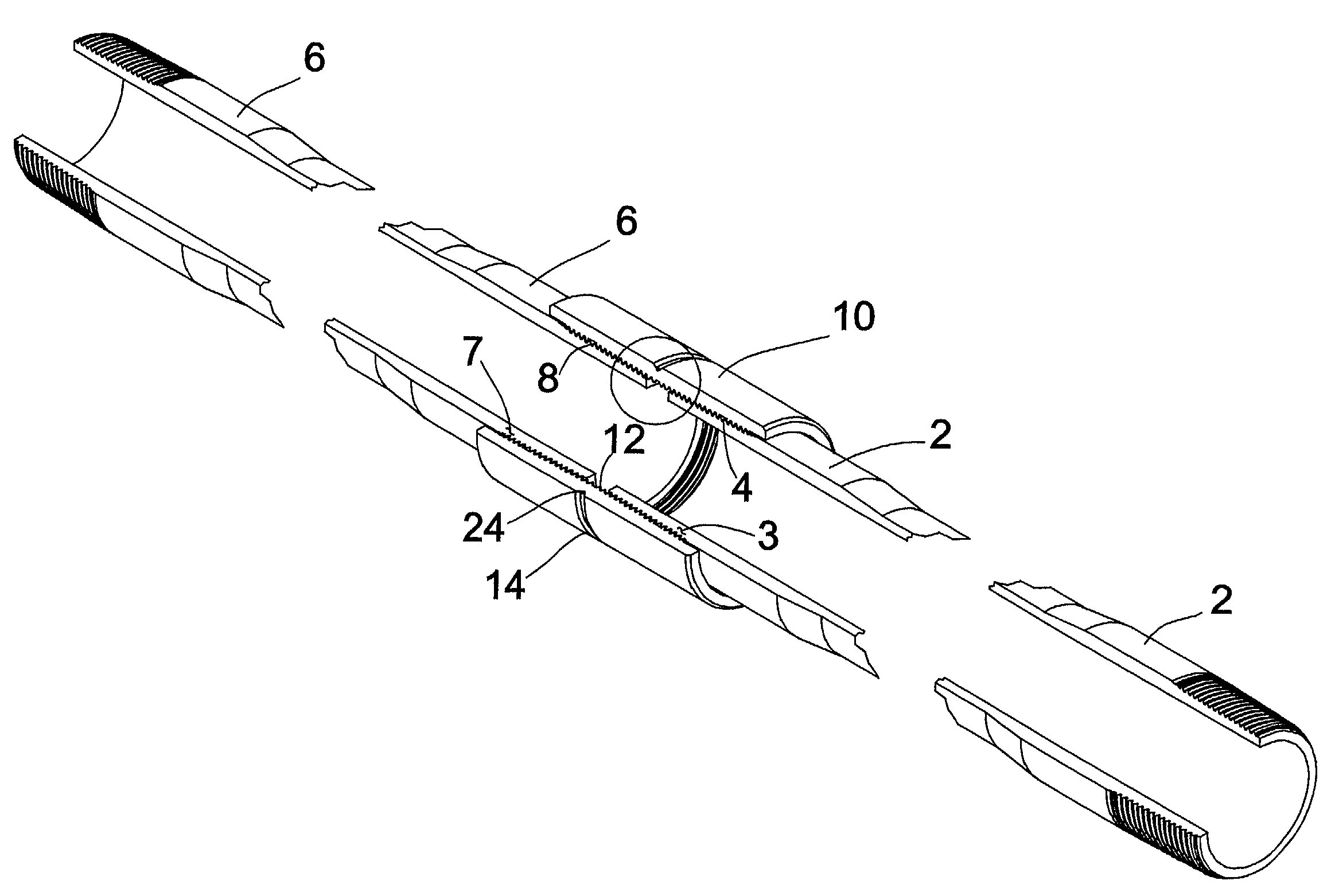
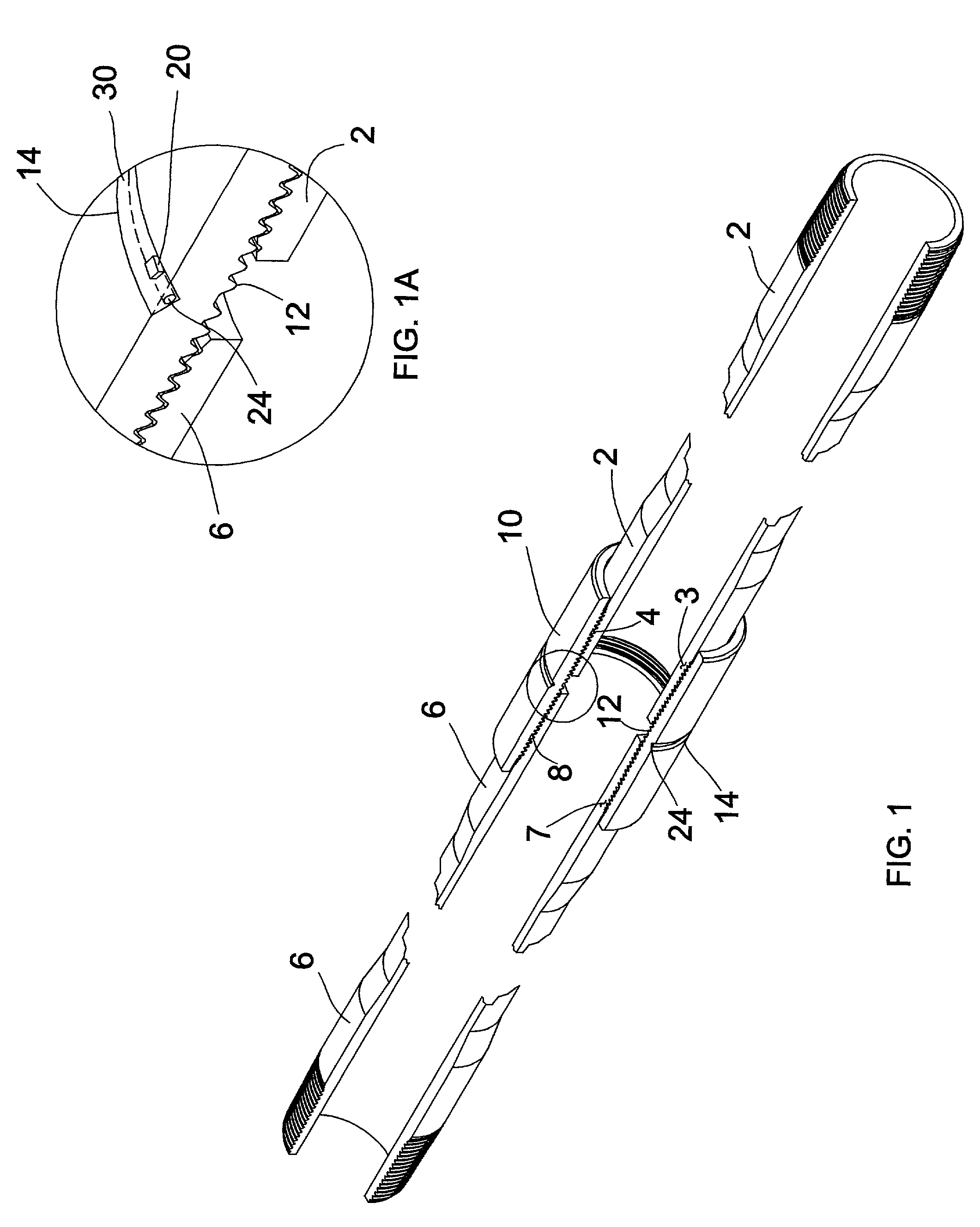
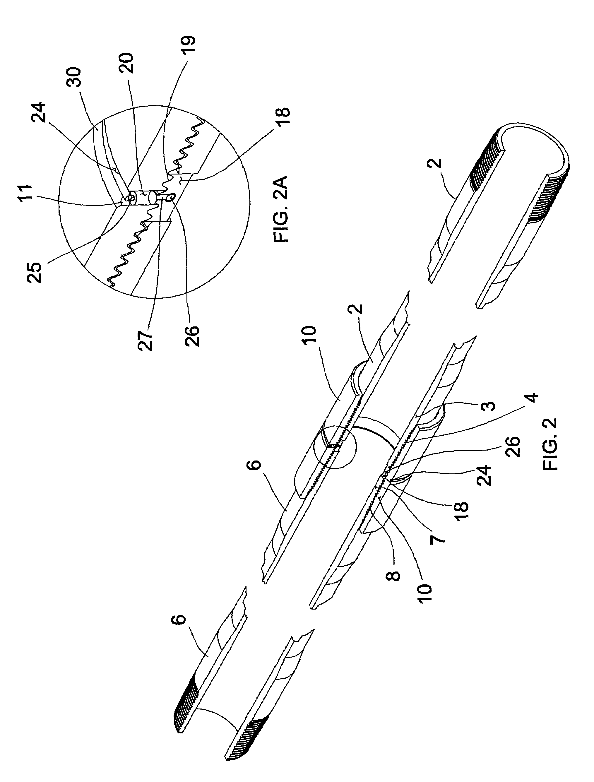
[0024]As utilized throughout this specification, the term “asset” refers to any article of manufacture or device, which includes, but is not limited to, tubulars, equipment and tools designed to be run on, connected to and / or operated by tubulars. As utilized throughout this specification, the term “tubular” refers to an individual length of any generally tubular conduit for transporting fluid, particularly oil, gas and / or water in and / or from a subterranean well and / or transportation terminal. When referring to a “tubular” which is used in a subterranean well, tubulars are usually secured together by means of collars to form a string of tubulars, such as a tubing string, drill string, casing string, etc., which is positioned in a subterranean well as utilized, at least in part, to transport fluids. Environments other than a subterranean well in which tubulars may be used in accordance with the present invention, include, but are not limited to, pipelines and sewer lines.

[0025]Refer...


PUM


Abstract

An assembly and process for identifying and tracking assets, particularly tubulars, equipment, tools and / or devices. An antenna is electrically connected to a responding device, such as a radio frequency identification device, and this assembly is connected to an asset. The antenna may be positioned about the exterior and / or the interior of the asset and significantly increases the range of signals that may be received and / or broadcast by the responding device. A transceiver may accordingly be positioned a greater distance from the asset without regard to the orientation of the asset and still permit communication between the transceiver and the responding device. In this manner, information that specifically identifies the asset may be compiled in a data base so as to maintain an accurate history of the usage of such assets as tubulars, equipment, tool and / or devices.

Description

CROSS REFERENCE TO RELATED APPLICATIONS[0001]This application is related to the following copending patent applications: U.S. patent application Ser. No. 09 / 586,648, filed on Jun. 1, 2000 and entitled “Method and System for Performing Operations and for Improving Production in Wells”; U.S. patent application Ser. No. 09 / 656,720, filed on Sep. 7, 2000 and entitled “Method and System for Performing a Casing Conveyed Perforating Process and Other Operations in Wells”; and U.S. patent application Ser. No. 10 / 032,114, filed on Dec. 21, 2001 and entitled “Method and Apparatus for Determining Position in a Pipe”.BACKGROUND OF THE INVENTION[0002]1. Field of the Invention[0003]The present invention relates to processes and assemblies for identifying and tracking assets, such as tubulars, equipment and tools used in subterranean wells, and more particularly, to processes and assemblies for identifying and tracking such assets which facilitates accurate input of data into a data base.[0004]2. ...

Claims


Application Information

Patent Timeline
IPC IPC(8): G06F17/00G01V1/00E21B17/00
CPCE21B17/006
Inventor ZIEROLF, JOSEPH A.
Owner WEATHERFORD TECH HLDG LLC
Learn More