Electronic device display system and method

a technology for electronic devices and display systems, applied in the direction of electric variable regulation, process and machine control, instruments, etc., can solve the problems of not being able to provide such a wide range of possible voltages using systems of the prior art without substantial modifications, power cables heavier and more expensive, and significant voltage drop relative to input voltag

Inactive Publication Date: 2006-03-21
POP DISPLAY LLC
View PDF18 Cites 97 Cited by
  • Summary
  • Abstract
  • Description
  • Claims
  • Application Information

AI Technical Summary

Problems solved by technology

Systems of the prior art have the disadvantage that they support only devices that can work with the set of voltages provided by the transformers of the base power supply, and updating the system to other different voltage levels for new devices to be displayed requires modification of the circuitry of the base.
It is not possible to provide such a wide range of possible voltages using systems of the prior art without substantial modifications.
Another drawback of the prior art is that the cable carrying power requires a number of wires, because there are three currents at different voltages, making the power cable heavier and more expensive.
Also, the length of the cord can result in a substantial drop in voltage relative to the input voltage, due to resistance in the cable, with the output voltage being less than the input voltage, and possibly outside the proper working voltage range for the associated electronic device.

Method used


Image

  • Electronic device display system and method
  • Electronic device display system and method
  • Electronic device display system and method

Examples


Embodiment Construction

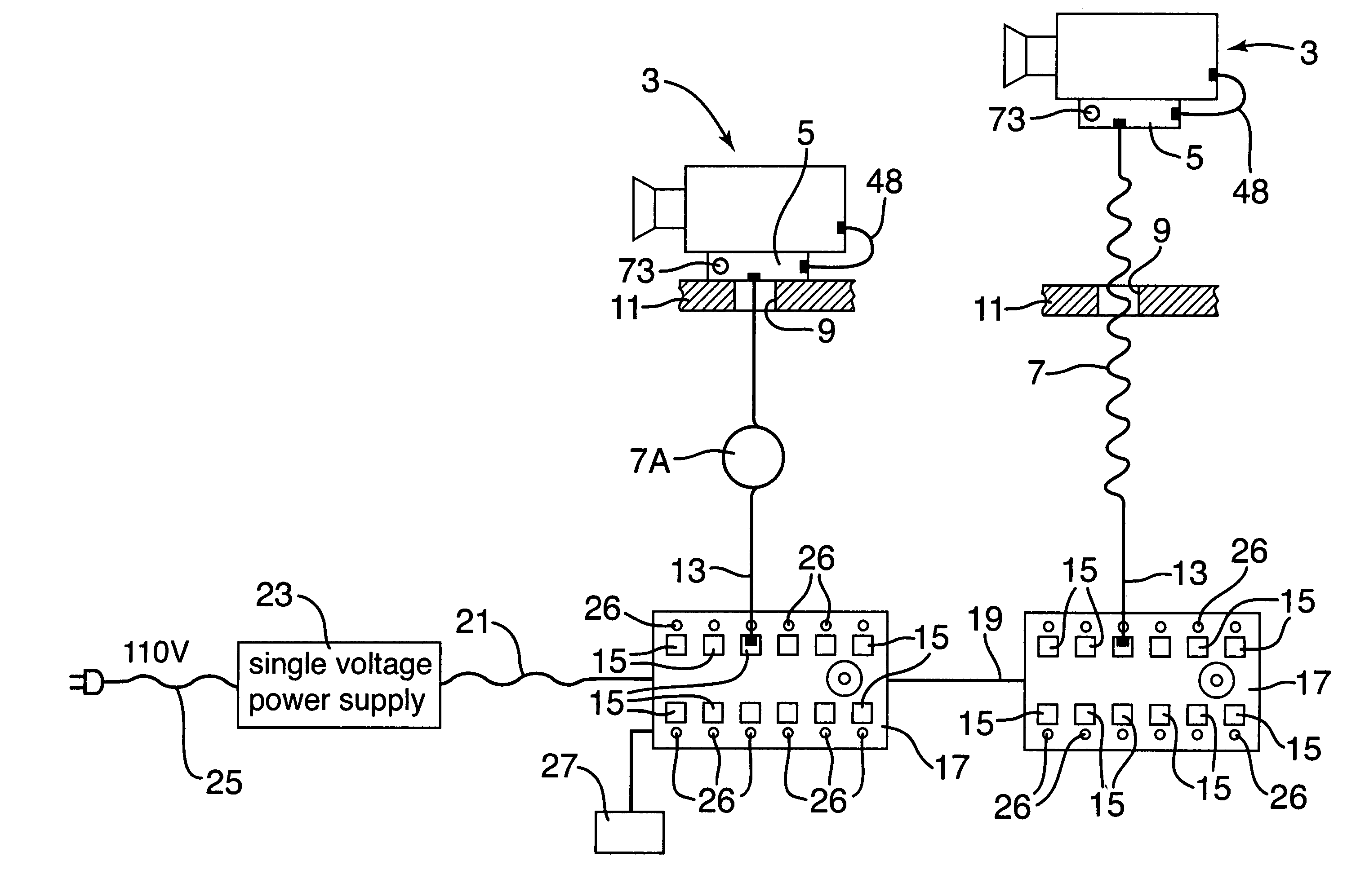
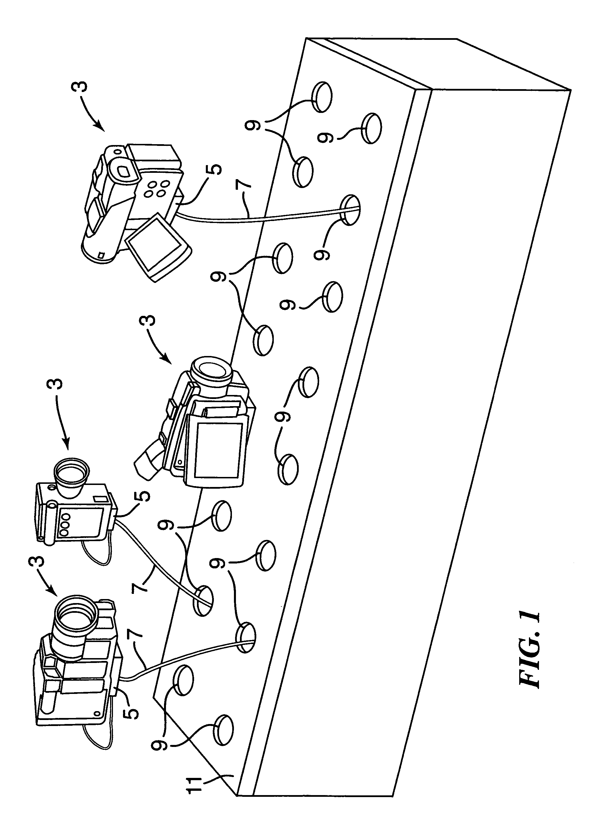
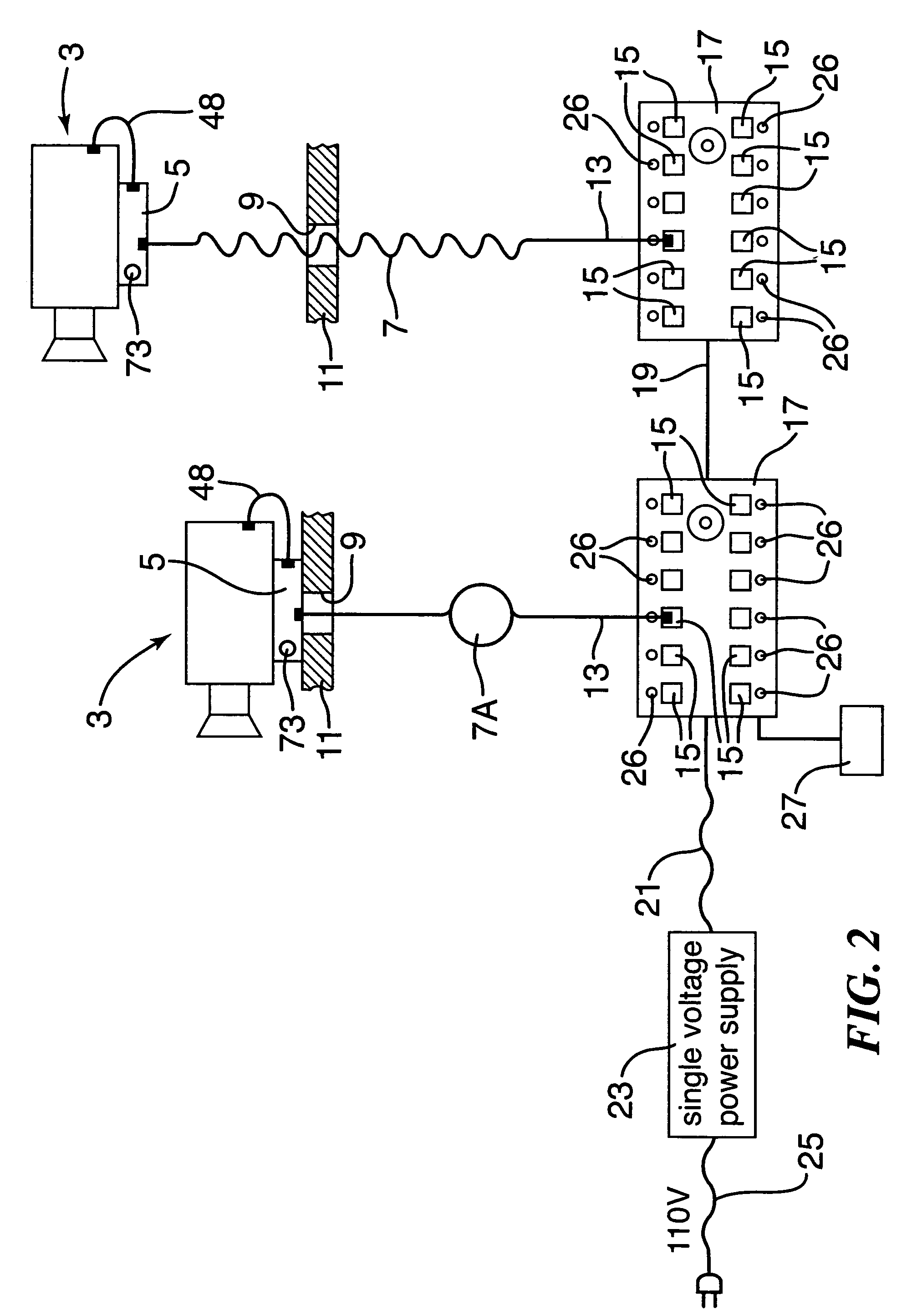
[0027]As best shown in FIGS. 1 and 2, an electronic device display is illustrated for displaying to customers one or more electronic devices 3, which in the preferred embodiments are camcorders or cameras, connected by cable structures to a base module.

[0028]Each camcorder 3 has secured thereto a device module or security circuit housing 5. The security module 5 has a connection structure or socket receiving the end of a flexible cable 7 that extends through an aperture 9 in a display cover plate 11, which encloses the display system so that the consumers do not see the power supply or other equipment supporting the display. The cable 7 is preferably a flexible coiled cable, or a cable with a spring loaded take-up reel or recoiler unit 7A.

[0029]The cable has a distal end 13 with a connection structure that is plugged into one of a number of modular connection structures or sockets 15 in one or more power supply base modules 17. The base modules 17 are connected to each other by an e...


PUM


Abstract

A system and method are provided for displaying electronic devices operable when electrical power is supplied to them at respective operating voltages through respective power connectors. The system has a power supply providing input electrical current at a first voltage and cable structures each connected with the power supply and having a respective power connector electrically connecting with the power receiving structure of one of the electronic devices. The cable structures each include a voltage regulator system that receives the input electrical current, converts it to an output electrical current at an output voltage, and transmits it to the power connector, so as to transmit an operating electrical current to the associated electronic device. The voltage regulator system sets the output voltage of the output electrical current such that the operating electrical current delivered to the associated electronic device has a voltage that corresponds to the operating voltage of that device. This is accomplished by connecting the voltage regulator to a calibrating component with a selected electrical characteristic that sets the output voltage. A security circuit creates an alarm when separation of the electrical device from the system occurs.

Description

RELATED APPLICATIONS[0001]This application asserts priority based on U.S. provisional patent application Ser. No. 60 / 485,263 filed by Opher Pail on Jul. 3, 2003.FIELD OF THE INVENTION[0002]This invention relates to the field of displays for electronic devices, and more particularly, to displays that support multiple devices to which electrical power is supplied for permitting consumers to try the equipment operating with electrical power. This invention especially relates to displays of multiple cameras or camcorders that customers in a store can actually use to select the best product to buy.BACKGROUND OF THE INVENTION[0003]Systems for displaying electronic devices in a store have been devised that supply electrical power to the devices so that a potential buyer can actually pick up and use the electronic device, such as a camcorder or camera, in the store before purchasing it, to select the best model for that particular customer.[0004]One such system is shown in U.S. Pat. No. 6,3...

Claims


Application Information

Patent Timeline
Patent Type & Authority Patents(United States)
IPC IPC(8): H02J1/10G08B13/14G09GH02G15/10H02M3/335
CPCG08B13/1454G08B13/1409
Inventor PAIL, OPHER
Owner POP DISPLAY LLC
Why Eureka
Try Eureka