
Vehicle tag reader

a technology of vehicle tag and reader, which is applied in the direction of devices using time traversed, instruments, transportation and packaging, etc., can solve the problems of unpractical wire-based solutions to communication problems, unwanted performance variations, and shortage of teachings

Inactive Publication Date: 2006-03-21
MINERAL LASSEN
View PDF66 Cites 17 Cited by
  • Summary
  • Abstract
  • Description
  • Claims
  • Application Information

AI Technical Summary

Benefits of technology

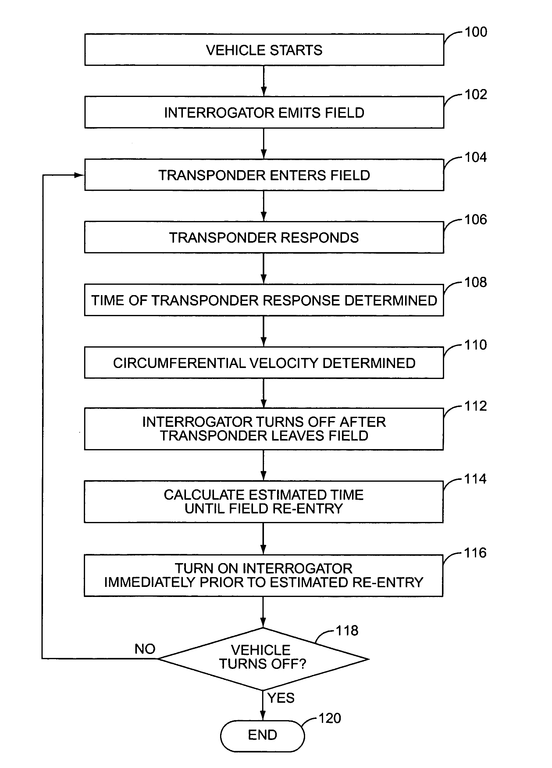
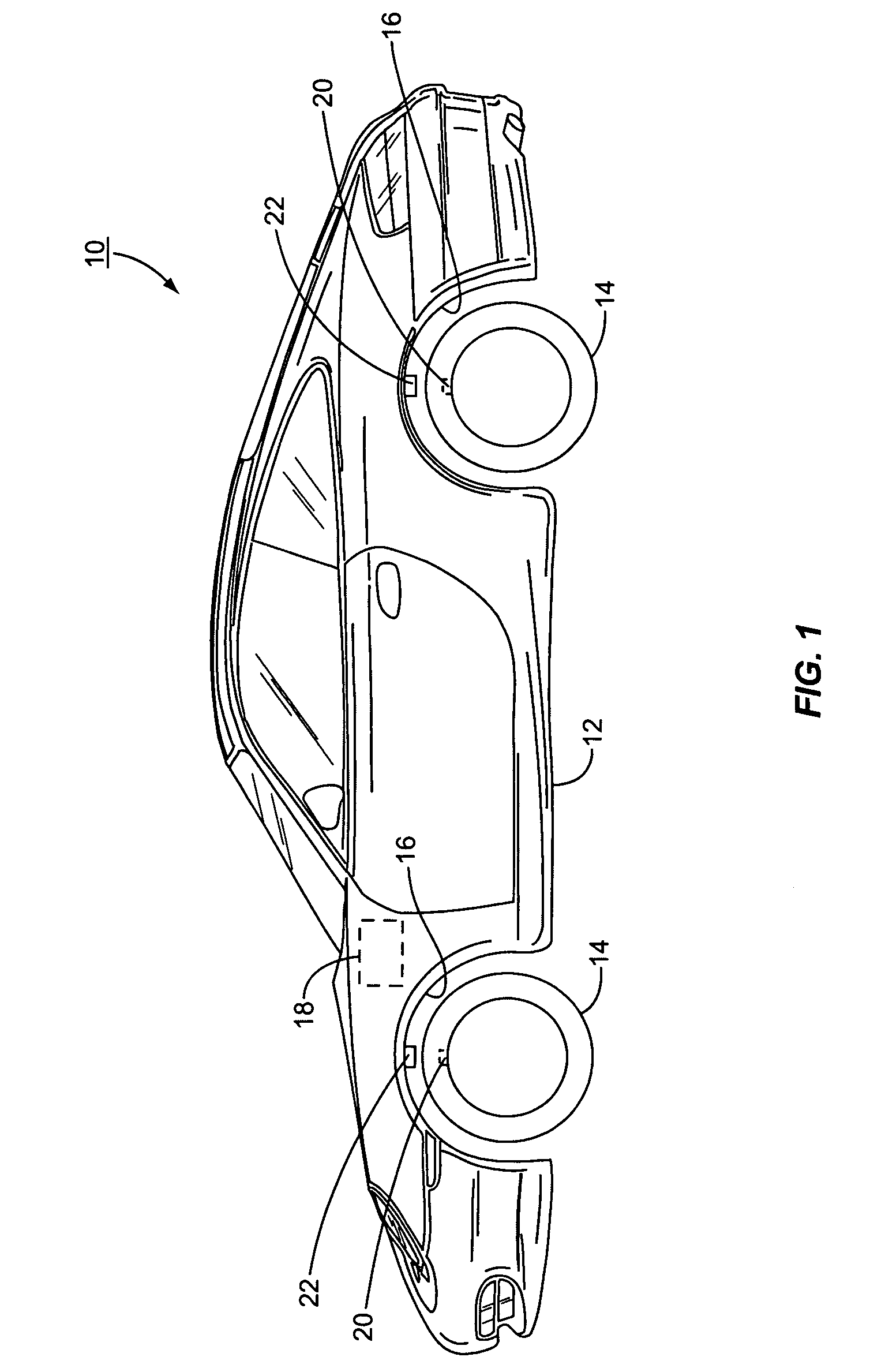
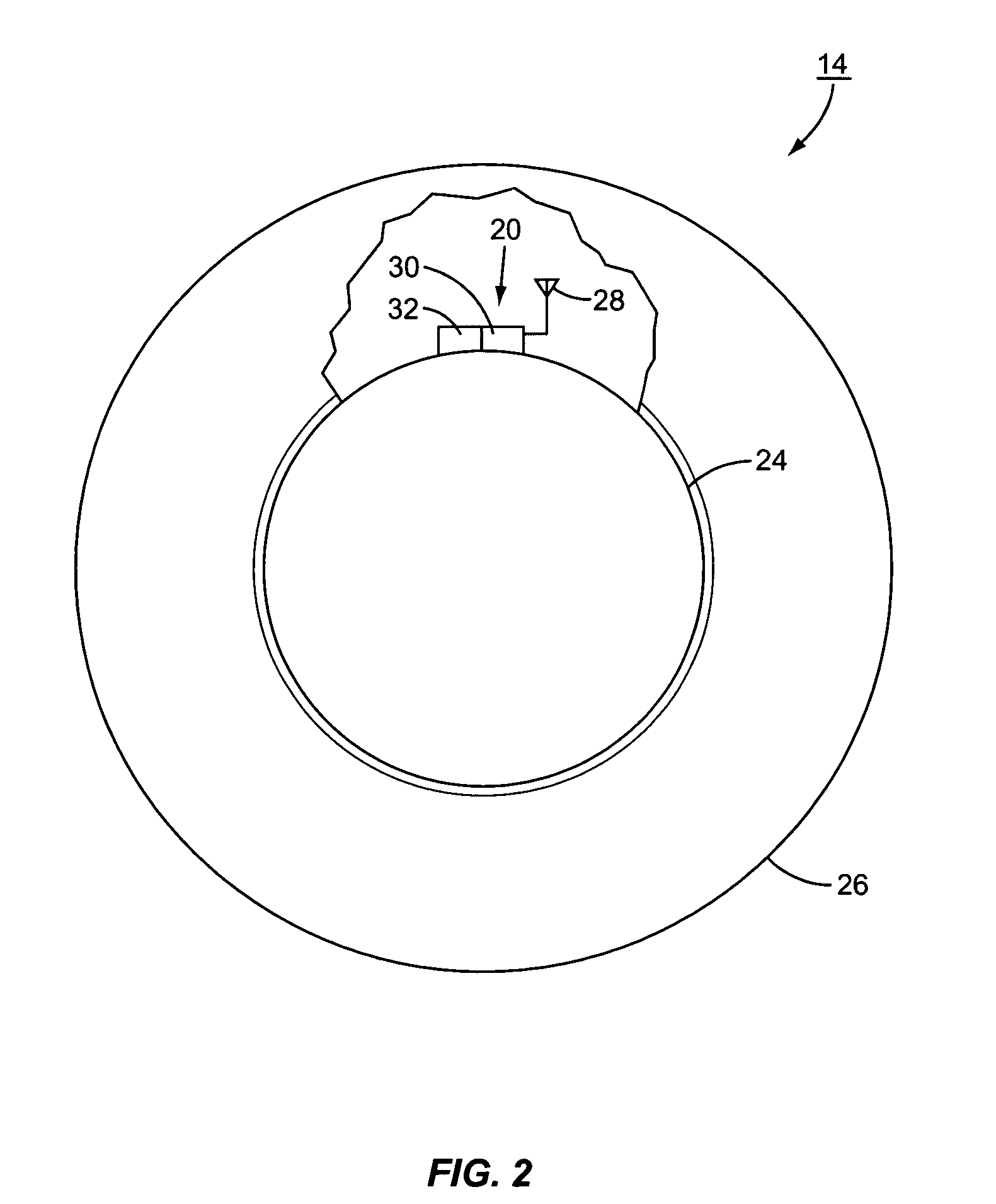
[0005]The present invention relates to use of a wireless communication device on a tire for monitoring tire conditions and the reporting of these tire conditions using an interrogation device. Monitoring of tire conditions on a vehicle may be performed when the vehicle is in rest or in motion. Special considerations must be made when using an interrogation reader on a vehicle to detect tire conditions via a transponder or RFID associated with a tire. The transponder on the tire may not always be in range of the interrogation reader during the tire's rotation when the vehicle is in motion. Two aspects of the present invention are designed to give vehicle designers more options when using interrogators and transponders to monitor tire pressure in vehicles. The last aspect introduces additional functionality into the transponder.
[0010]Exemplary techniques to determine the location of the transponder involve interfacing with the vehicle control system to learn the orientation of the wheel and empirically determining the location and interfacing with the vehicle control system to track its location with speed changes. Coupled with this aspect are some structural variations in the antenna structure designed to promote a more efficient communication between the transponder and the interrogator.

Problems solved by technology

Unintended changes in the pressure within the tires of the vehicle may cause unwanted performance variations.
These performance variations may include not only fuel consumption variations, but also safety concerns.
Because of the rotation of the tires, wire-based solutions to the communication issue are impractical.
To date, there has been a shortage of teachings in ways to distribute the interrogator within a vehicle.

Method used


Image

  • Vehicle tag reader
  • Vehicle tag reader
  • Vehicle tag reader

Examples


third embodiment

[0030]FIG. 3C illustrates a third embodiment, in which the baseband processor 38 and the demodulator 36 are integrated into the vehicle controller 18. Only the antenna 34 is positioned in the wheel well 16. Raw, undemodulated signals and power pass to and from the antenna 34 and the baseband processor 38 over the link 44.

[0031]Together, these three embodiments provide a variety of options for designers to use when incorporating interrogators into vehicles. As noted earlier, provision of more options provides more flexibility for the designers and improves the likelihood that an acceptable design may be located that meets the design criteria of the designer. Note that these three embodiments do not match the INTERMEC device, but with the teachings of the present invention the components of the INTERMEC device could be split into such an arrangement by one of ordinary skill in the art.

[0032]With this background of hardware, some of the other aspects of the present invention may now be...

first embodiment

[0035]Since the location and speed of the transponder 20 is known, the antenna need only communicate with the transponder 20 over a narrower arc of rotation of the wheel 14. Further, multiple antennas may be fired sequentially based on the known position and speed, thereby addressing any distortion concerns. Two such antenna structures 70 are illustrated in FIGS. 5 and 6. In FIG. 5, a plurality of transmit antennas 72 are used in conjunction with a single receive antenna 74. In the embodiment shown, five transmit antennas 72A–72E are illustrated, although it should be appreciated that fewer or more transmit antennas 72 may be used if needed or desired. The transmit antennas 72A–72E generate corresponding electromagnetic lobes 76A–76E. The lobes 76A–76E are narrow and extend sufficiently far to reach the expected location of the transponder 20. The transponder 20 responds with an electromagnetic signal that is received by the receive antenna 74. Because the reflected signal from the ...

second embodiment

[0036]A second embodiment, illustrated in FIG. 6, of antenna structure 70 arranges a plurality of dual function antennas 78A–78E about the wheel well 16. Each antenna 78 both transmits and receives an electromagnetic signal with a focused lobe 80. As the transponder 20 moves through the field of view of the antennas 78, the antennas may sequentially alter functions to achieve the maximum downlink, transmit, critical path, adequate uplink and receive. For example, initially the first antenna 78A may be in a transmit mode while second antenna 78B was in a receive mode. The remaining antennas 78C–78E may be disconnected. As the transponder 20 moves in front of the second antenna 78B, then the second antenna 78B is used to transmit, while first and third antennas 78A and 78C are used to receive. The remaining antennas 78D and 78E remain disconnected. The transponder 20 may then move into lobe 80C, effectively being in front of third antenna 78C, so third antenna 78C is used to transmit ...


PUM


Abstract

A remote communication device, such as a radio frequency type device, that receives temperature indicia concerning a container and / or its contents and communicates such temperature indicia along with an identification indicia to a reader. The remote communication device can measure and communicate temperature indicia associated with a container in a periodic manner. The remote communication device can also measure and communicate temperature indicia associated with a container when such temperature indicia exceed a certain minimum or maximum threshold temperature. The remote communication device can also include power circuitry to store energy when energized in the range of an interrogation reader so that the remote communication device can be powered for temperature indicia measurements when not in the range of an interrogation reader. The temperature associated with the container and / or its contents may be determined by various techniques including thermal contact between the temperature sensor and the container, measuring the discharge rate in a discharge capacitor associated with the remote communication device, and determining the frequency of maximum energy absorption of the remote communication device to correlate it to temperature.

Description

FIELD OF THE INVENTION[0001]The present invention relates to wireless communication devices associated with vehicle tires for the purposes of reporting tire conditions.BACKGROUND OF THE INVENTION[0002]As vehicles become more complex, vehicle designers change more and more parameters to modify performance and improve safety. One parameter that may be modified to change performance is the pressure within the tires of the vehicle. Unintended changes in the pressure within the tires of the vehicle may cause unwanted performance variations. These performance variations may include not only fuel consumption variations, but also safety concerns. Several efforts have been made to allow monitoring of the pressure in vehicle tires. In addition to merely monitoring the pressure in the tires, there is also a need to communicate the data from the monitoring to a location where the information may be used.[0003]Because of the rotation of the tires, wire-based solutions to the communication issue ...

Claims


Application Information

Patent Timeline
Patent Type & Authority Patents(United States)
IPC IPC(8): B60C23/00B60C23/02G08C17/02B60C23/04B60C23/20
CPCB60C23/0408G01P3/66B60C23/0444
Inventor FORSTER, IAN J.
Owner MINERAL LASSEN
Learn More