Load balancing for raster image processing across a printing system

a printing system and load balancing technology, applied in the field of processing and transfer of data, can solve the problems of reducing the operating speed of the print engine, reducing the production of the printer, and the print system which offloads all the rip responsibility to the host computer, and other performance issues

Active Publication Date: 2006-03-21
HEWLETT PACKARD DEV CO LP
View PDF7 Cites 102 Cited by
  • Summary
  • Abstract
  • Description
  • Claims
  • Application Information

AI Technical Summary

Benefits of technology

[0007]The present invention is preferably embodied in a method and apparatus which dynamically determines on a job-by-job, or, alternatively, a page-by-page, basis if the raster image processing (RIP) for a print job data file is more efficiently performed by the host computer or by the printer in a printing system to provide printed output at the maximum rated print engine capacity. The method according to the present invention monitors the entire printing process and, based on a model for estimating the time required for various component print processes, determines where the RIPping of the next print job data file should be performed to balance the processing load across the printing system to best utilize the maximum printing speed of the printer print engine.

Problems solved by technology

However, increasingly more and more complex graphics print jobs require longer times for the formatter board to process thus reducing the rate at which data is transferred to the print engine resulting in reduced operating speeds for the print engine and reduced production for the printer.
This is particularly a problem in commercial printing or commercial printing environments where it is important for the print production operators (i.e., personnel) to run the printers at the maximum capacity for large volume print output.
On the other hand, a print system which offloads all the RIP responsibility to the host computer encounters other performance issues.
While the RIPped data file can be compressed prior to being transmitted to the printer, the size of that data file can still be significant.
This results in two problems: first, an increase in the transmission time over the communication link between the host computer and the printer; and second, an increase in the time required by the printer to decompress and process the large amount of data in the RIP file.

Method used


Image

  • Load balancing for raster image processing across a printing system
  • Load balancing for raster image processing across a printing system
  • Load balancing for raster image processing across a printing system

Examples


Embodiment Construction

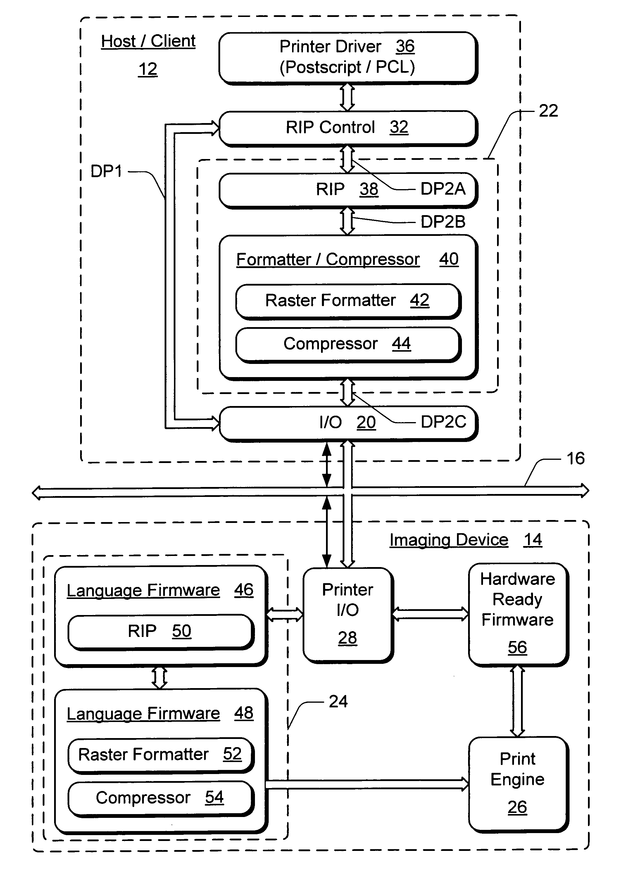
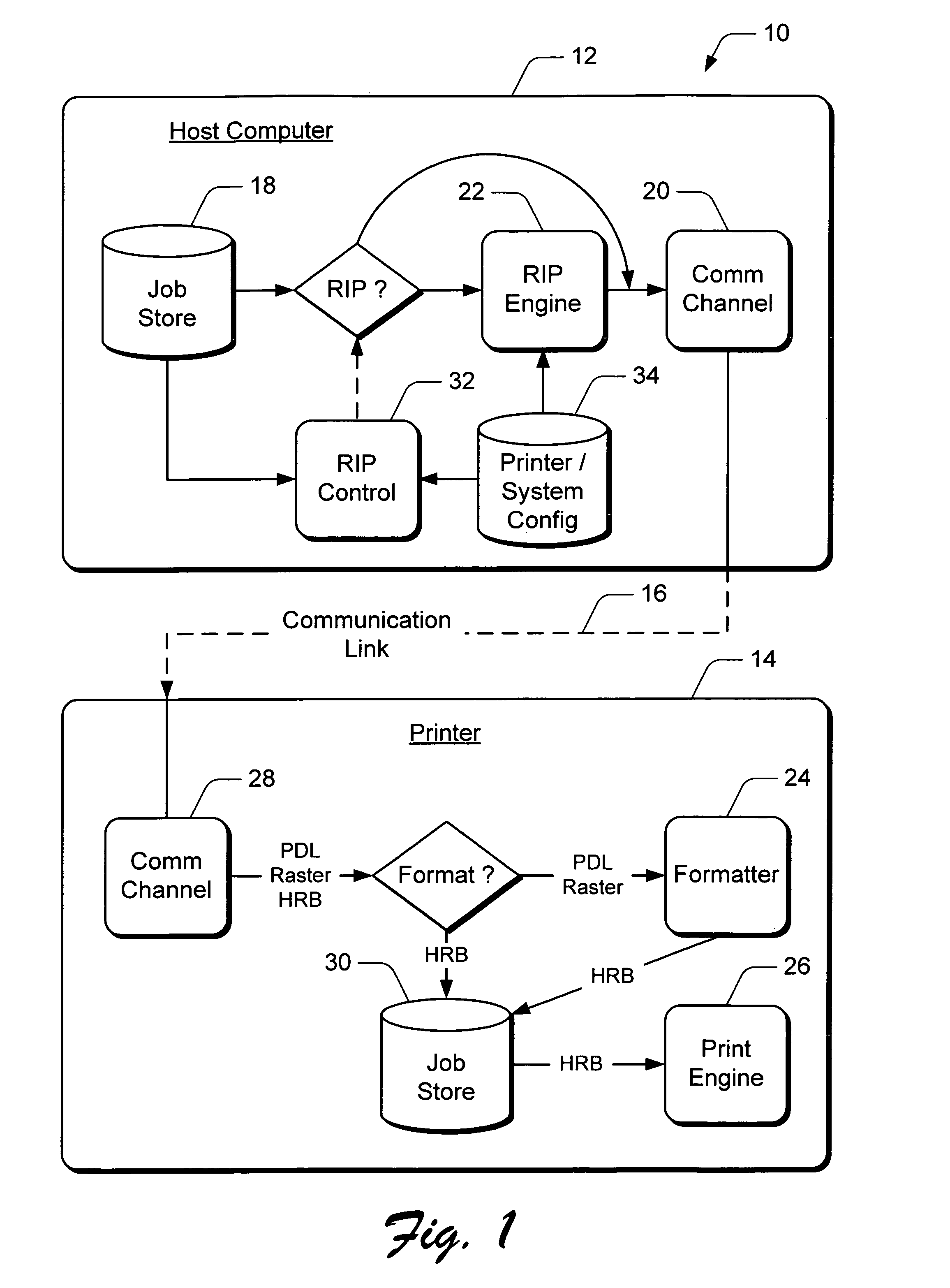
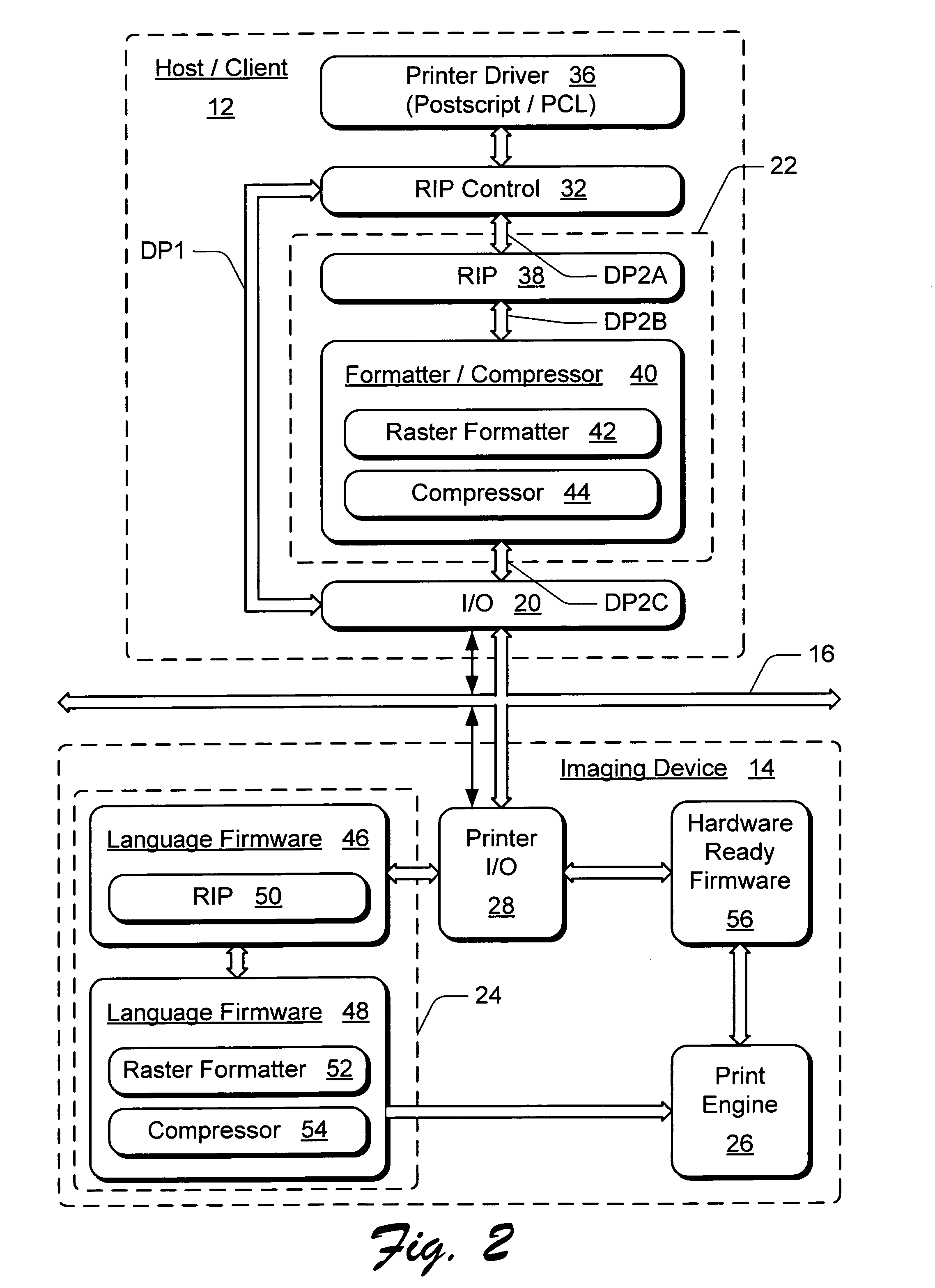
[0016]As shown in the drawings for purposes of illustration, the present invention is preferably embodied in a method and apparatus which dynamically determines on a job-by-job, or, alternatively, a page-by-page, basis if the raster image processing (RIP) for a print job data file is more efficiently performed by the host computer or by the printer in a printing system to provide printed output at the maximum rated print engine capacity. The method according to the present invention monitors the entire printing process and, based on a model for estimating the time required for various component print processes, determines where the RIPping of the next print job data file should be performed to balance the processing load across the printing system to best utilize the maximum printing speed of the printer print engine. In a preferred embodiment, the method of the present invention directs the print job data processing (RIP) at either a host computer or an imaging device to ensure tha...


PUM


Abstract

A method and apparatus which dynamically determines if the raster image processing (RIP) for a print job data file is more efficiently performed by the host computer or by the printer in a printing system. The entire printing process is monitored and, based on a model for estimating the time required for various component print processes, a determination is made where the raster processing of the print data for the next print job should be performed to balance the processing load across the printing system to best utilize the maximum printing speed of the printer print engine.

Description

FIELD OF THE INVENTION[0001]The present invention relates generally to the processing and transfer of data, and, more particularly, to a method of balancing the data processing load between a hard copy output device such as a printer and a host computer in a printing system to achieve a maximum output within the capability of the print engine.BACKGROUND OF THE INVENTION[0002]In a printing system, such as those employing laser or inkjet printers, for example, the data representing an image that is to be printed must be converted to a raster format in order for the printer print engine to be able to deposit pixels, sometimes referred to as “pels”, of toner or ink on a print media. Prior art printers include rendering systems that reside in a printer. For example, most printers include a formatter board which is a combination of hardware and firmware to accomplish this rendering task, commonly referred to as RIPping (i.e., Raster Image Processing). At a host computer, application softw...

Claims


Application Information

Patent Timeline
Patent Type & Authority Patents(United States)
IPC IPC(8): G06F15/00G06F3/12
CPCG06F3/1213G06F3/1214G06F3/1286G06F3/126G06F3/1247
Inventor HEWITT, JAMES A.
Owner HEWLETT PACKARD DEV CO LP
Why Eureka
Try Eureka