Low-gain regenerative amplifier system

a laser amplifier and low-gain technology, applied in the direction of laser details, optical resonator shape and construction, active medium materials, etc., can solve the problems of large fluctuations, poor isolation, and limited energy of laser oscillators that produce ultra-fast pulses, and achieve the effect of increasing the contrast ratio of amplified pulses

Active Publication Date: 2006-03-21
NEWPORT CORP
View PDF13 Cites 10 Cited by
  • Summary
  • Abstract
  • Description
  • Claims
  • Application Information

AI Technical Summary

Benefits of technology

[0012]Another object of the present invention is to provide low-gain regenerative amplifiers, and their methods of use, that have an improved contrast ratio.
[0014]Yet another object of the present invention is to provide low-gain regenerative amplifiers, and their methods of use, that do not allow the undesired seed pulses to enter the regenerative amplifier and pass through the gain, therefore maximizing the gain available for the desired seed pulse.
[0016]In another embodiment of the present invention, a method is provided for producing an amplified pulse from a regenerative amplifier system. A pump beam is produced from a pump source. Multiple seed pulses are produced from the oscillator. A single seed pulse is selected for the cavity. The seed pulse is switched in and out of the cavity. An amplified pulse produced in the cavity is directed in a direction away from the oscillator. This increases the contrast ratio of the amplified pulse to the pre-pulses.

Problems solved by technology

The laser oscillators that produce these ultrafast pulses are often limited in the energy per pulse that they can produce with a typical energy being 1 to 100 nanojoules.
This poses a severe problem since ultrafast oscillators are very sensitive to feedback.
Reflection of as little as 1% of the light output from the oscillator back into the oscillator can cause instability and large fluctuations.
Occasionally, prior art systems have used a 4% reflector instead of the Faraday isolator, however this does a poor job of isolation.
A new problem occurs however, when a single Pockels cell and polarizer are used.

Method used


Image

  • Low-gain regenerative amplifier system
  • Low-gain regenerative amplifier system
  • Low-gain regenerative amplifier system

Examples


Embodiment Construction

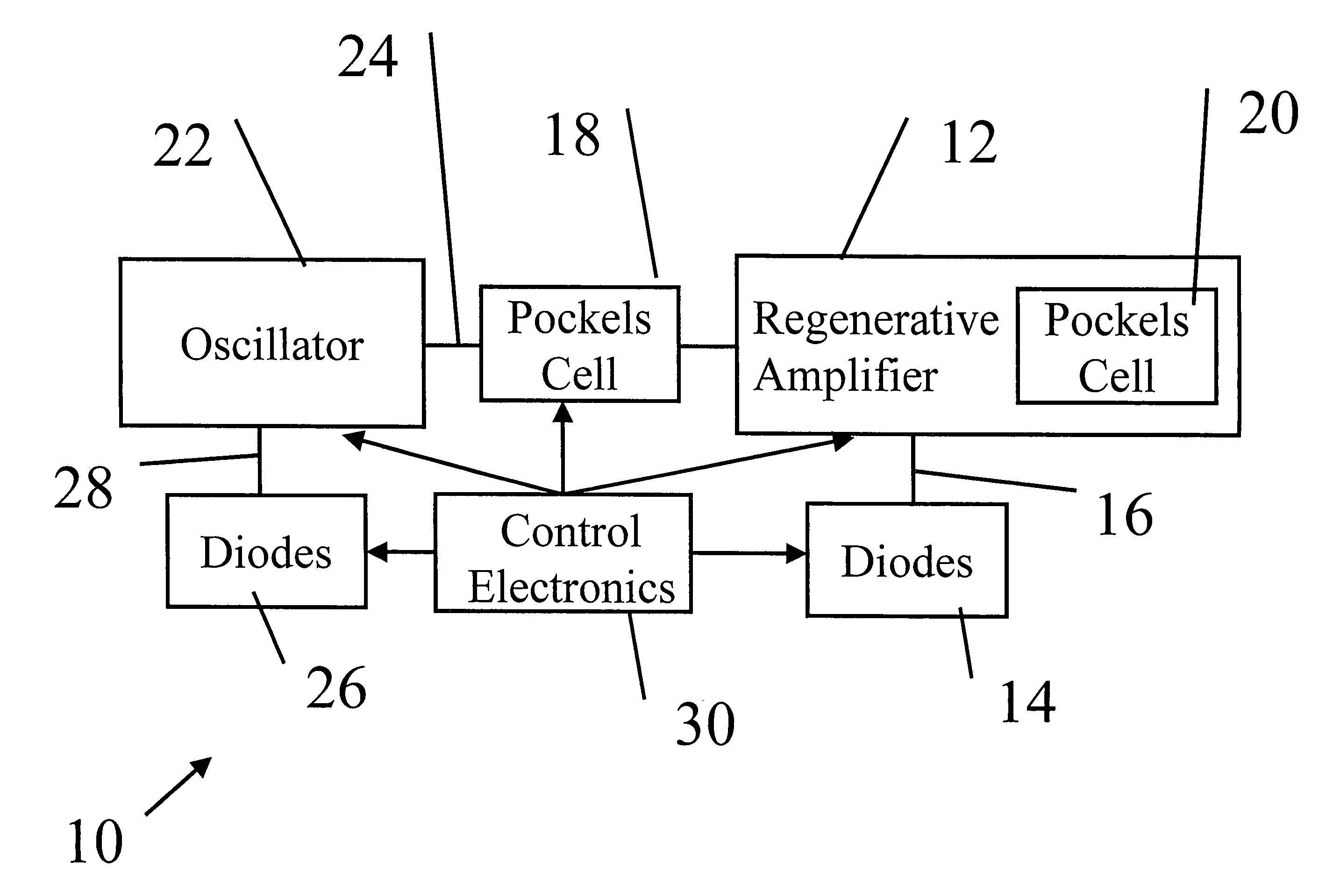
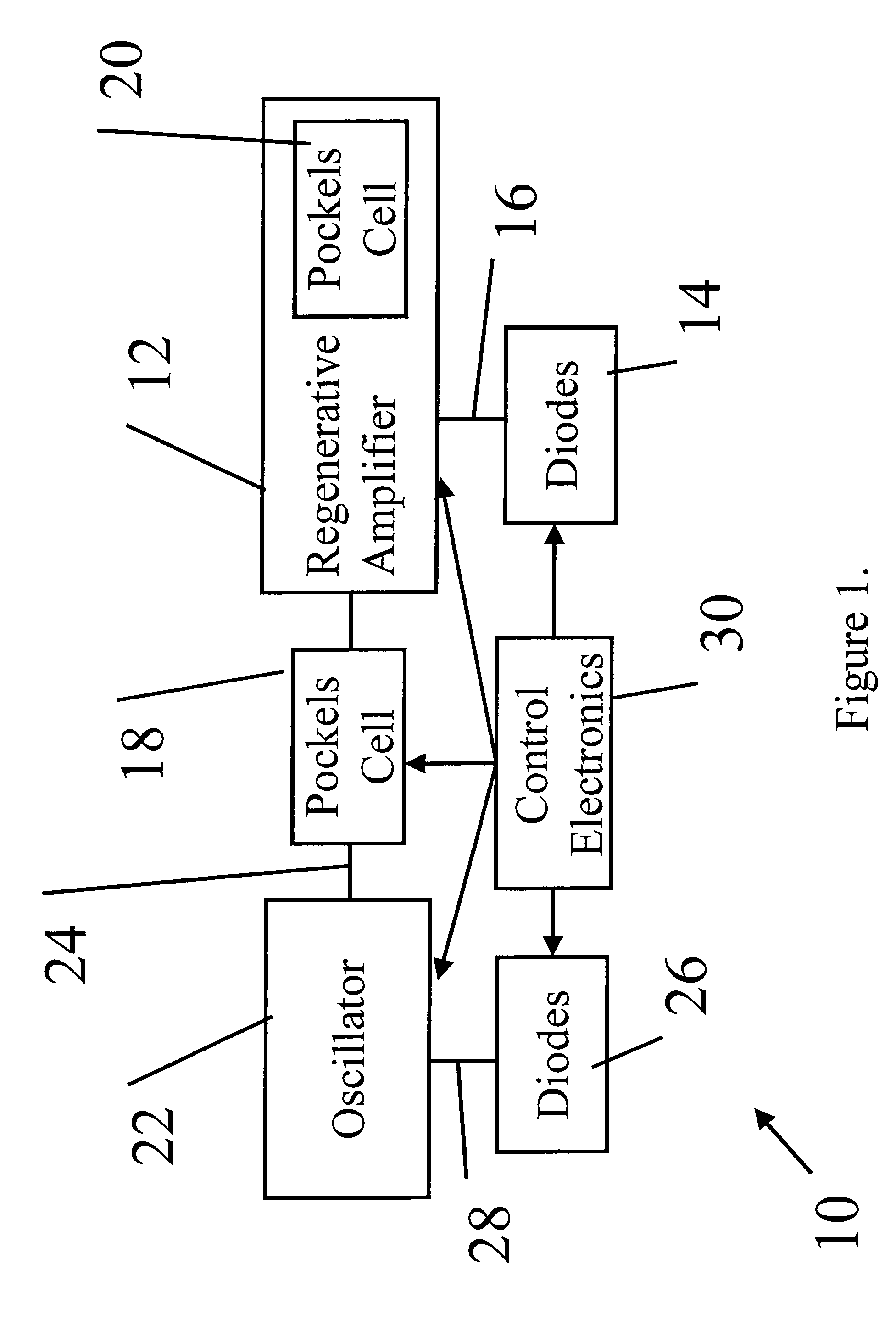
[0023]As illustrated in FIG. 1, in one embodiment of the present invention, a regenerative amplifier system, generally denoted as 10, includes a regenerative amplifier cavity 12 and a pump source 14 that produces a pump beam 16. The power of pump beam 16 can vary. In various embodiments, pump beam 16 can a power in the range of, of 1–100 W, 1–30 W, 1–10 W, and the like. The amount of pump power is selected depending on the output power desired. Pump beam 16 can have a variety of wavelengths, including but not limited to a wavelength in the range of 800 to 1000 nm.

[0024]A first electro-optic switch 18 is positioned external to regenerative amplifier cavity 12 (hereafter “cavity 12”). A second electro-optic switch 20 is positioned in cavity 12. An oscillator 22 is coupled to first electro-optic switch 18 and produces multiple seed pulses 24.

[0025]A pump source 26 produces a pump beam 28 for oscillator 22. In various embodiments, pump source 26 can be selected from a diode, a diode bar...


PUM


Abstract

A regenerative amplifier system that is optimized for low-gain gain media is provided. The system is configured to include a minimum number of intra-cavity elements while still eliminating the leakage of the seed pulses from the output beam. In addition, the contrast ratio of the amplified pulses is increased even considering the long build-up time that is required in low-gain regenerative amplifiers. This is accomplished using a single Pockels cell between the oscillator and amplifier to select a single seed pulse for the cavity, instead of using a Faraday isolator. This directs the unwanted seed pulses in a separate direction from the output pulse. When the amplified pulse exits the cavity, it is directed in a direction away from the oscillator by the same Pockels cell. Only one additional Pockels cell and one polarizer are required inside the regenerative amplifier cavity.

Description

BACKGROUND OF THE INVENTION[0001]1. Field of the Invention[0002]This invention relates generally to a regenerative laser amplifier system and its methods of use, and more particularly to a low-gain regenerative amplifier system with a simplified configuration that eliminates the leakage of the seed laser.[0003]2. Description of Related Art[0004]Regenerative amplifiers are typically used to increase the energy of an optical pulse. These pulses can be of any duration but a particularly useful range includes ultrafast pulses with picosecond or femtosecond duration. The laser oscillators that produce these ultrafast pulses are often limited in the energy per pulse that they can produce with a typical energy being 1 to 100 nanojoules. A regenerative amplifier for these ultrafast pulses can increase the energy to the millijoule range, a gain of 106.[0005]A regenerative amplifier contains a gain medium surrounded by a resonant cavity. Within this cavity are means for switching the pulse in...

Claims


Application Information

Patent Timeline
Patent Type & Authority Patents(United States)
IPC IPC(8): H01S3/00H01S3/16H01S3/23
CPCH01S3/235H01S3/0064H01S3/0085H01S3/107H01S3/1618H01S3/1611
Inventor KAFKA, JAMES D.ZHOU, JIANPINGHOLSINGER, KEVIN
Owner NEWPORT CORP
Why Eureka
Try Eureka