Image signal coding method, image signal coding apparatus and storage medium

a signal coding and image technology, applied in the field of image signal coding methods and apparatuses, can solve the problems of blurred background sprite image generated by background sprite images, inability to accurately estimate global motion parameters between images,

Active Publication Date: 2006-03-21
PANASONIC CORP
View PDF14 Cites 77 Cited by
  • Summary
  • Abstract
  • Description
  • Claims
  • Application Information

AI Technical Summary

Benefits of technology

[0008]It is an object of the present invention to provide a method and apparatus for generating a b...

Problems solved by technology

However, in the above method, when the foreground has a motion different from the background, it is not possible to accurately e...

Method used


Image

  • Image signal coding method, image signal coding apparatus and storage medium
  • Image signal coding method, image signal coding apparatus and storage medium
  • Image signal coding method, image signal coding apparatus and storage medium

Examples


embodiment 1

[0032](Embodiment 1)

[0033]FIG. 2 shows a configuration of an image signal coding apparatus in Embodiment 1 of the present invention. In image signal coding apparatus 1, an input color image shot by color camera 2 is input to layer section 4, while a depth image shot by range finder 3 is input to layer section 4.

[0034]Range finder 3 outputs the depth image (image obtained by mapping depth values from the camera in pixel gray scale) from the same viewpoint as in the color image. FIG. 3 shows an example of a configuration of range finder 3. In range finder 3, light source section 3A irradiates object H with a near-infrared laser slit light, while the light is swept horizontally, and reflected lights from object H are picked up in near-infrared camera 3C through narrow-bandwidth optical filter (interference filter) 3E and lens 3B.

[0035]An output of near-infrared camera 3C is input to depth calculating section 3D. The sweeping of the slit light projects a pattern light by controlling lig...

embodiment 2

[0059](Embodiment 2)

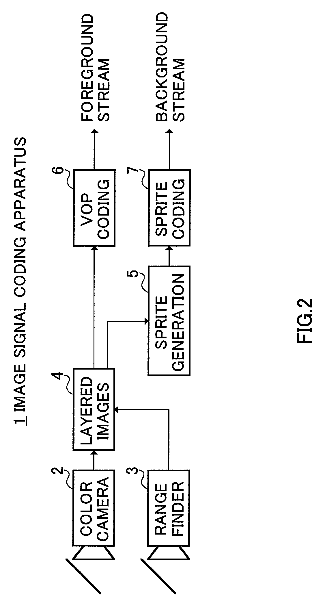
[0060]FIG. 9 shows a configuration of image signal coding apparatus 30 according to Embodiment 2 of the present invention with similar portions to FIG. 2 assigned the same reference numerals as in FIG. 2. Image signal coding apparatus 30 has the same configuration as that of image signal coding apparatus 1 in Embodiment 1 except that sprite extending section 31 is provided between sprite generating section 5 and sprite coding section 7.

[0061]As shown in FIG. 10, in a background sprite image, with respect to a region in which pixel values are not written due to interception of foreground, when pixels in which pixel values are written exist in the vicinity of such a region (i.e., when a target pixel exists in a region indicated by “A” in FIG. 10), sprite extending section 31 extrapolates the pixel values at the pixel-value-written pixels and thereby extends the background sprite image.

[0062]By thus extending the background sprite image by one or two pixels, when a ...

embodiment 3

[0065](Embodiment 3)

[0066]FIG. 11 shows a configuration of image signal coding apparatus 40 according to Embodiment 3 of the present invention with similar portions to FIG. 2 assigned the same reference numerals as in FIG. 2. In image signal coding apparatus 40, the foreground image and background image obtained in layer section 4 are input to region boundary correcting section 41.

[0067]Region boundary correcting section 41 extends the foreground edge by extending processing performed as a general image processing technique to correct the boundary between the foreground and background. FIG. 12 is an explanatory diagram for region boundary correcting processing. FIGS. 12A and 12B respectively show a foreground image and background image prior to the region boundary correction, and FIGS. 12C and 12D respectively show a foreground image and background image subjected to the region boundary correction. In FIGS. 12A and 12B, region A is separated erroneously as background despite region ...


PUM


Abstract

Provided are a depth image obtaining section that obtains a depth image from the same viewpoint as in the input image, a layer section that separates the input image into a foreground image and a background image as layered images using depth information of the depth image, a coding section that encodes the foreground image, a background sprite generating section that generates a background sprite image from the background image, and a sprite coding section that encodes the background sprite image. The depth image from the same viewpoint as in the input image is obtained in the depth image obtaining section, the input image is separated into a foreground image and a background image as layered images using the depth information, and based on the separated background image, a background sprite image is generated.

Description

BACKGROUND OF THE INVENTION[0001]1. Field of the Invention[0002]The present invention relates to an image signal coding method and apparatus that generate a sprite image from moving images.[0003]2. Description of the Related Art[0004]In recent years, sprite images have been used as a technique of achieving interactive graphical display on games and the internet. One of conventional techniques of generating a sprite image from moving images is described in JP2000-148130.[0005]According to the description, a sprite image is generated as shown in FIG. 1. First, instep (hereinafter referred to as ST) 1, moving images including portions shot by camera operations such as panning and zooming are input. In ST2, global motion parameters (parameters representing the motion of the entire image) are extracted from the moving images. In ST3, a base frame for generating a sprite is determined in the moving images.[0006]In ST4, predictive images are generated by operating the global motion paramet...

Claims


Application Information

Patent Timeline
IPC IPC(8): H04N7/12H04N19/50G06T7/00H04N5/272H04N19/23H04N19/503H04N19/51H04N19/57H04N19/597H04N19/85
CPCG06T7/004G06T7/70H04N5/272
Inventor AZUMA, TAKEONOBORI, KUNIOUOMORI, KENYAMORIMURA, ATSUSHI
Owner PANASONIC CORP
Why Eureka
Try Eureka