Optically integrated device

a technology of integrated devices and optical components, applied in the field of optical integrated devices, can solve the problems of limited luminous efficiency of optical integrators, limited luminous efficiency of image processing devices, and loss of portion of light l due to color filters b, so as to achieve the effect of increasing the amount of unnecessary elements and enhancing the luminous efficiency

Inactive Publication Date: 2006-03-21
UNITED MICROELECTRONICS CORP
View PDF9 Cites 2 Cited by
  • Summary
  • Abstract
  • Description
  • Claims
  • Application Information

AI Technical Summary

Benefits of technology

[0010]According to the above description of the background of the invention, it is one objective of the present invention to provide an optically integrated device that recycles the reflected light by redesigning the relationship between the optical integrator and the color filter to enhance the luminous efficiency without increasing the amount of unnecessary elements. The color filters filter and reflect the light at the same time.
[0011]It is an another objective of the present invention to provide an image-processing device with a high luminous efficiency by redesigning the relationship between the optical integrator and the color filter without increasing the volume of the image-processing device.
[0012]It is a further objective of the present invention to provide an image-processing device with a high luminous efficiency by collecting the light to economize the cost of the production that enhances the luminous efficiency in the prior art.
[0013]The present invention provides an optically integrated device with low light loss by attaching or forming a color filter on the optical integrator to filter through a portion of the light, and reflect the other portion of the light back to the optical integrator. The optically integrated device recycles the reflected light inside the optical integrator to prevent the light loss to enhance the luminous efficiency.

Problems solved by technology

So that the luminous efficiency of the optical integrator is limited due to the lost light L′.
Moreover, a portion of the light L may be lost due to the color filter 11.
Because the multiple colors are included in color wheel 11, the reflected light L0′ is lost which limits the luminous efficiency of the image-processing device.

Method used


Image

  • Optically integrated device
  • Optically integrated device
  • Optically integrated device

Examples


first embodiment

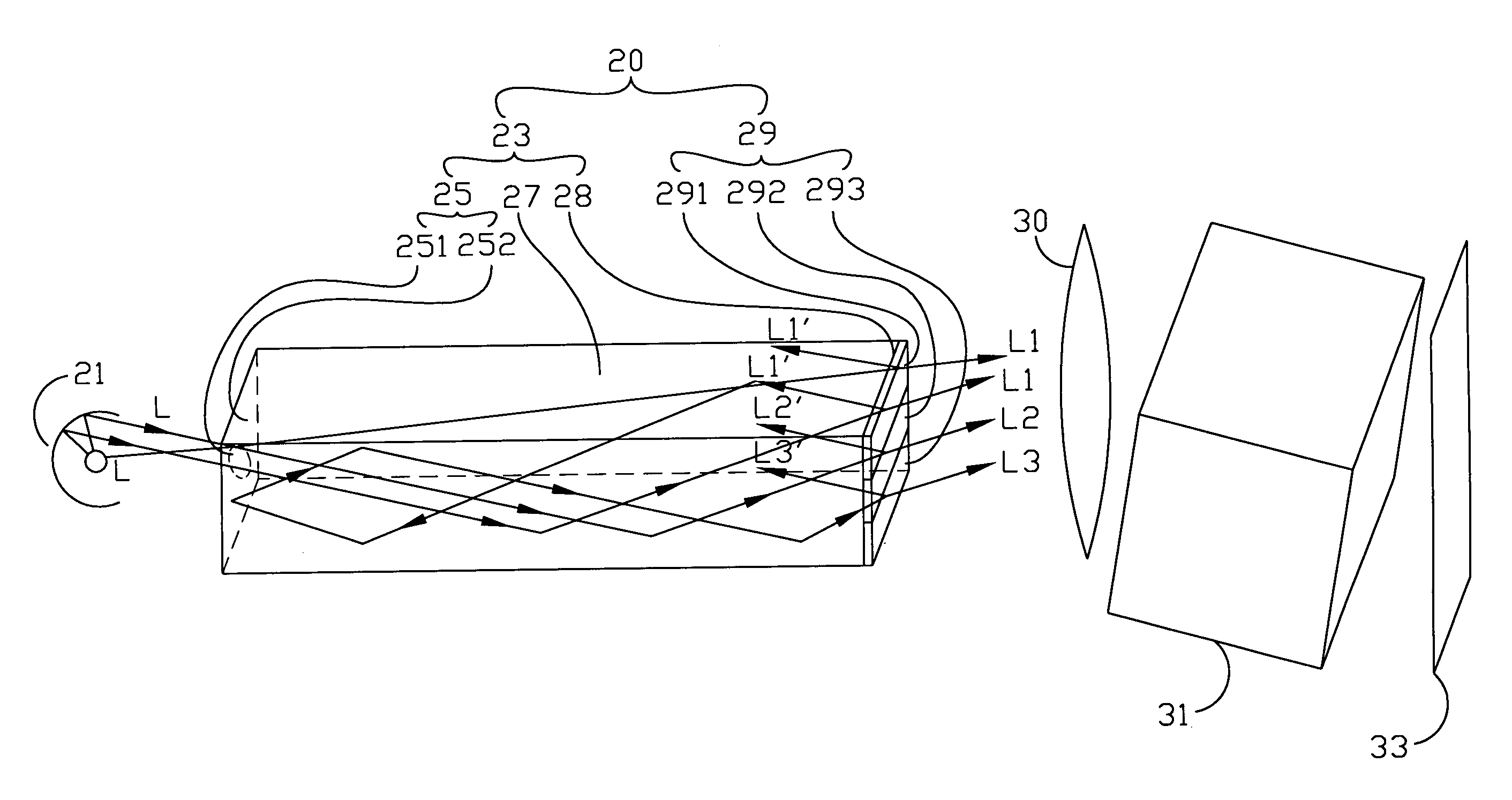
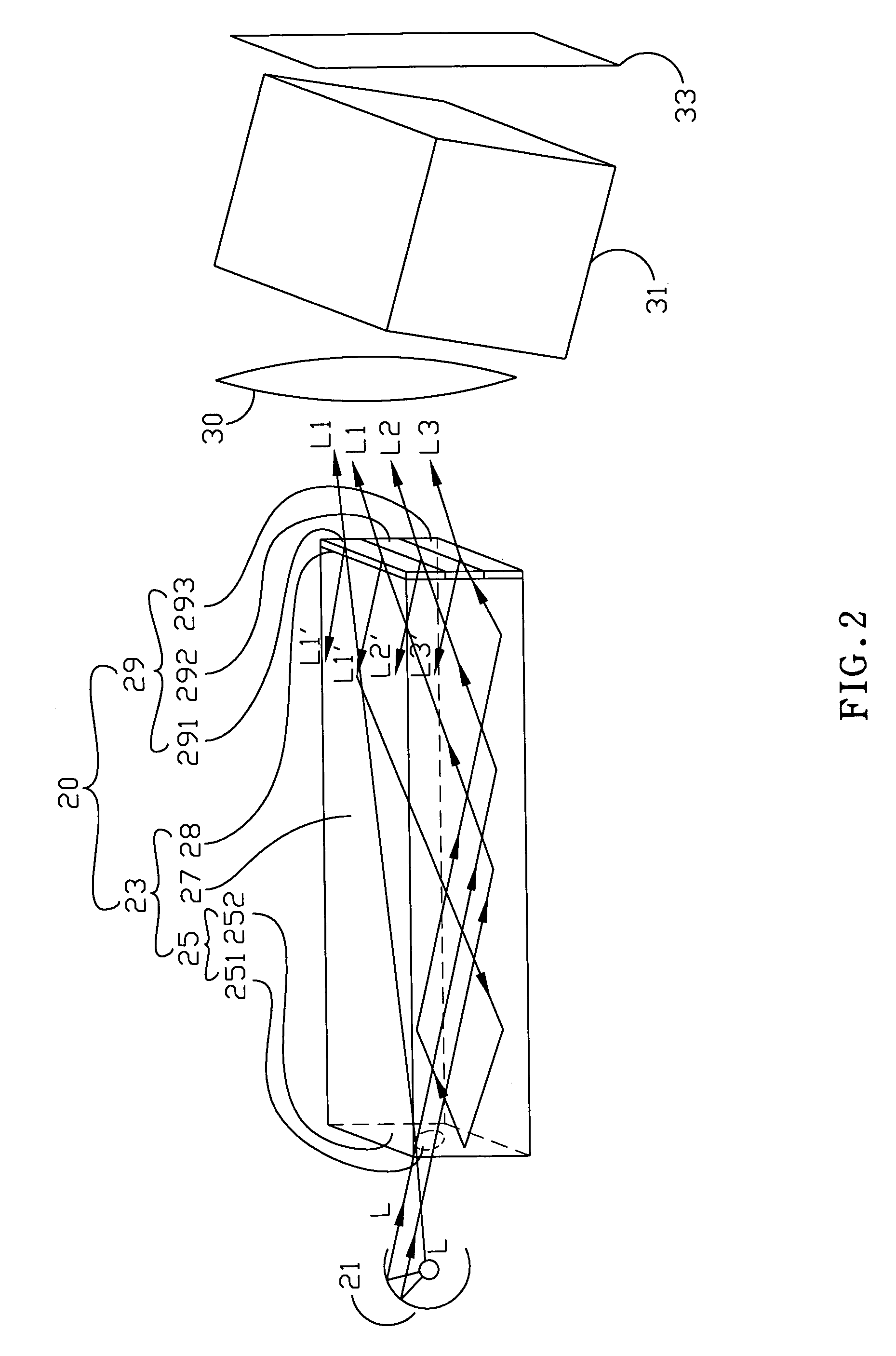
[0021]A three-dimensional perspective view of the first embodiment is shown in FIG. 2. An image-processing device includes a light source 1, an optically integrated device 20 and an image-forming system that includes a scrolling prism 31 and an imaging face 33. The image-forming system may include a light-condensing element 30, i.e. a lens, for condensing light. The optically integrated device 20 is set between the light source 1 and the image-forming system.

[0022]The optically integrated device 20 includes the optical integrator 23 and the color filter 29 that includes multiple colors, i.e. Red, Green and Blue, wherein the layout of the colors is different according to the different designed optically integrated device. The optical integrator 23 includes a light inputting face 25, a light outputting face 28 and a reflective part 27. The color filter 29 is adhered on the light outputting face 28, wherein the color filter 29 includes a color filter 291, a color filter 292 and a color...

second embodiment

[0028]The optical integrator 23 may be a different shape as shown in FIG. 3. The optical integrator 23 of the present invention is a tapered cylinder. The shape of the optical integrator 23 may be different from all shapes of the preferred embodiments described above.

[0029]As shown in FIG. 3, the optical integrator 23 includes a light inputting face 25 and a reflective part 27 without a light inputting face. The optically integrated device 20 includes the optical integrator 23, that is a hollow hexahedron, and a color filter 29, that is fixed on the optical integrator 23. The color filter 29 may be a color selective panel, a spectroscope, or another device could filter through the color of the light.

[0030]The optically integrated device includes the color filter that is attached on the optical integrator to filter through a portion of the light, and to reflect the other portion of the light back to the optical integrator. The optically integrated device recycles the reflected light,...


PUM


Abstract

The present invention relates to an optically integrated device, and more particularly, to an optically integrated device with low light loss. A color filter is attached to an optical integrator to filter through a portion of the light, and reflect the other portion of the light back to the optical integrator. The optically integrated device recycles the reflected light inside the optical integrator to prevent light loss.

Description

BACKGROUND OF THE INVENTION[0001]1. Field of the Invention[0002]The present invention relates to an optically integrated device, and more particularly, to an optically integrated device with a high luminous efficiency.[0003]2. Description of the Prior Art[0004]The optical system is improved as fast as the science develops. How to enhance the luminous efficiency, use low power consumption and remain the same volume of the optical system is very important. For example, the DLP (Digital Light Processing) image-processing system has the advantages of the high luminous efficiency and a small volume.[0005]As shown in FIG. 1, the optical integrator 3 of the DLP image-processing system is a pillar with four side surfaces and two end surfaces. There is a rectangular light inputting face 5 on an end surface, and at the other end surface is a light outputting face 9. A reflective part 7 is distributed over the side surfaces. When the light L is emitted from the light source 1, a portion of the...

Claims


Application Information

Patent Timeline
Patent Type & Authority Patents(United States)
IPC IPC(8): G02B6/00F21V8/00G02B6/42G02B27/09
CPCG02B6/0001G02B27/0994G02B6/4298
Inventor CHIANG, PO-LIANGTSAI, HSIN-WEN
Owner UNITED MICROELECTRONICS CORP
Why Eureka
Try Eureka