Magnetic powder torque transfer clutch for controlling slip across a differential mechanism

a torque transfer clutch and magnetic powder technology, applied in the direction of non-deflectible wheel steering, process and machine control, underwater equipment, etc., can solve the problems of low slip across the clutch, heat dissipation due to frictional contact, etc., to achieve short aggregate engagement time of the clutch, high long-term durability of the clutch, and low friction

Active Publication Date: 2006-03-21
FORD GLOBAL TECH LLC
View PDF7 Cites 14 Cited by
  • Summary
  • Abstract
  • Description
  • Claims
  • Application Information

AI Technical Summary

Benefits of technology

[0013]An advantage of the invention is high long-term durability of the clutch because aggregate engagement time of the clutch is short and there is little wear of clutch surfaces. Torque reduction in the mechanism can be accomplished using gears, chains, belts, higher speed gearing. The mechanism is simple and employs an inexpensive control that relies on the appropriate speed ratio of axle half shafts.
[0014]The torque required after gearing-up both front and rear axles is readily realizable at low electrical power expenditure, size and weight. In addition, the clutch uses concentric cylinders, which allows engagement at essentially any automotive axle speed. It is well known that centrifugation is not a problem with this geometry.
[0015]Because the energy dissipated by the clutch is the product of the relative rotational rate of the two clutch members and the torque produced, heat buildup is low and completely manageable at the desired low slip rates. Heat dissipation due to frictional contact and slip across the clutch is low.
[0016]In realizing these and other advantages, a method according to the present invention controls wheel slip across a differential mechanism of a motor vehicle having a vehicle speed, a steering angle and a steering direction, the differential mechanism including two rotating output shafts driveably connected to the wheels and connectable by a clutch that is activated by a magnetic field of variable strength to change a torque capacity of the clutch. The method includes comprising the steps of determining the current driveshaft speed, the magnitude and the direction of the current steering angle; determining a target speed of the output shafts that corresponds to the current driveshaft speed, steering angle and steering direction; determining the speeds of the output shafts; comparing the speeds of the output shafts and the target speeds to determine whether wheel slip is present; and adjusting the magnitude of the field strength to increase the torque capacity of the clutch and control the speed of the rotating shafts such that wheel slip is reduced.

Problems solved by technology

Heat dissipation due to frictional contact and slip across the clutch is low.

Method used


Image

  • Magnetic powder torque transfer clutch for controlling slip across a differential mechanism
  • Magnetic powder torque transfer clutch for controlling slip across a differential mechanism
  • Magnetic powder torque transfer clutch for controlling slip across a differential mechanism

Examples


Embodiment Construction

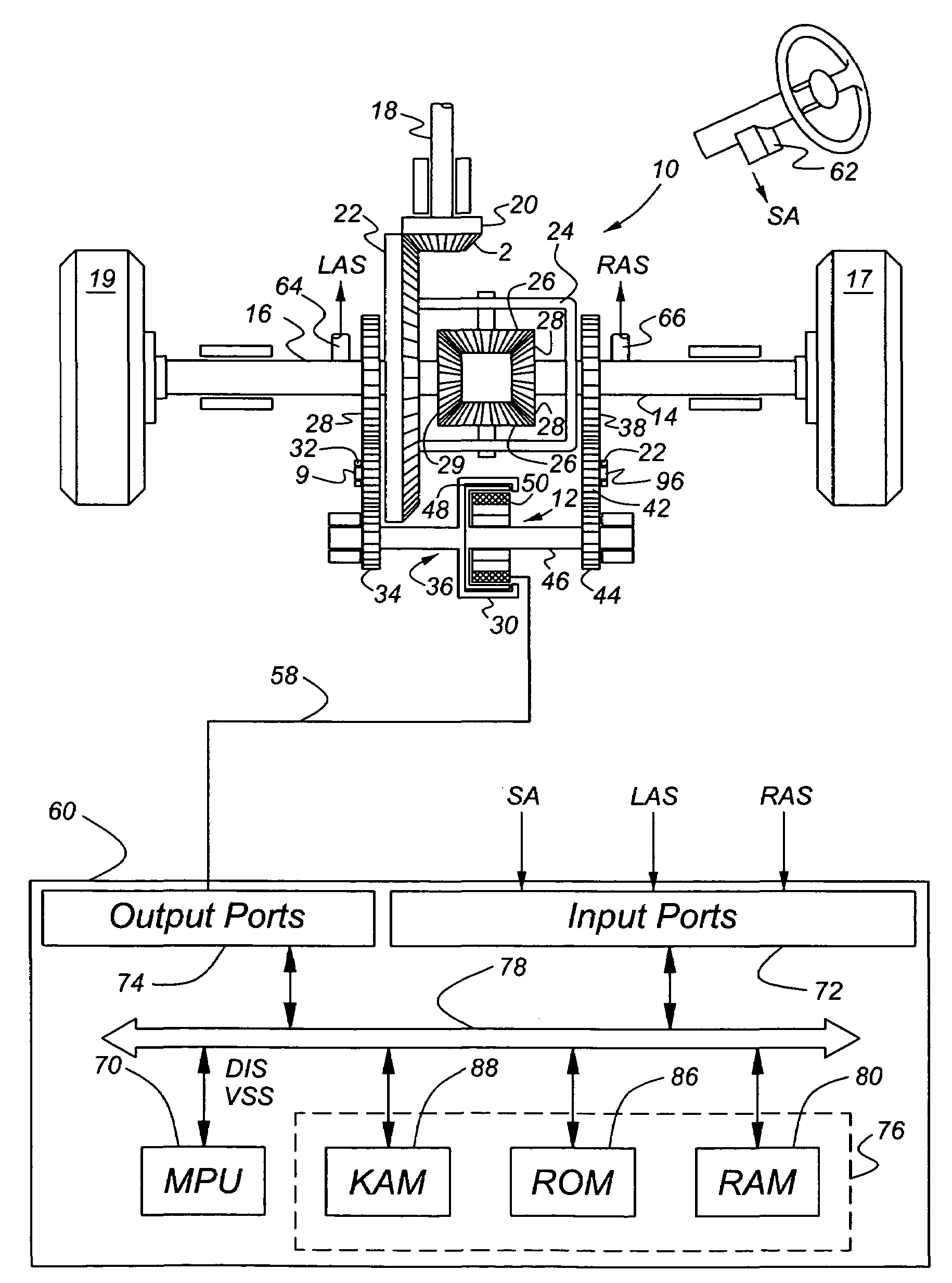
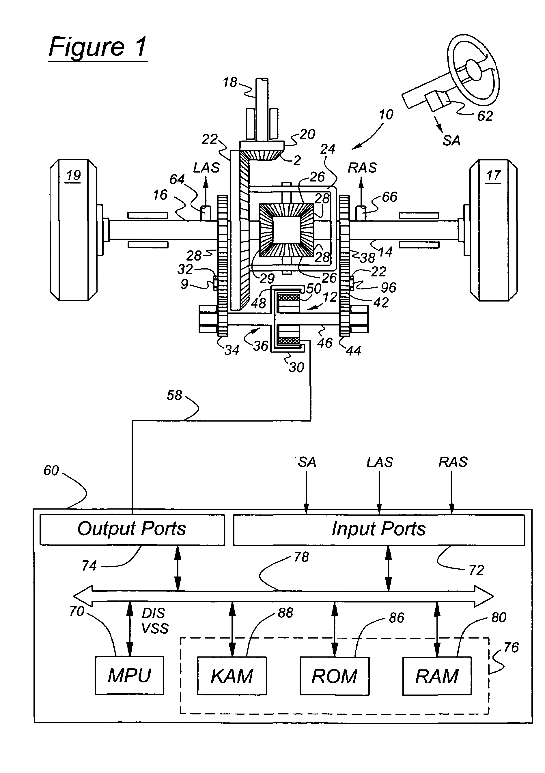
[0021]Referring now to the drawings, there is illustrated in FIG. 1 a schematic diagram of a rear wheel drive, limited slip differential mechanism 10 and a gearset controlled by clutch 12, which is actuated by selective creation of a magnetic field operating on magnetic powder contained in the clutch. The clutch and its associated control determine the relative magnitudes of torque supplied to right-hand and left-hand axle shafts 14, 16. All shafts in this design are supported rotatably by appropriately sized bearings.

[0022]An engine or another power source (not shown) is driveably connected to a transmission, which produces a range of gear ratios some of which increase the speed and reduce the torque at the transmission output relative to those of the engine output. Some of the gear ratios produced by the transmission decrease the speed and increase the torque at the transmission output relative to those of the engine output.

[0023]The transmission output is driveably connected to a...


PUM


Abstract

A control for a differential including magnetic powder torque transfer clutch for controlling slip across the differential mechanism. The clutch includes a first element driveably connected to a first control shaft, a second element driveably connected to the second output shaft, chamber bounded by the first and second elements, magnetic powder located in the chamber; and an elecromagnetic coil producing a magnetic field of variable strength passing through the chamber and magnetic powder and changing a capacity of the clutch to transmit torque between the first and second control shafts as the field strength changes.

Description

BACKGROUND OF THE INVENTION[0001]1. Field of the Invention[0002]This invention relates to the control of torque transfer in a differential mechanism having a magnetic powder differential lock providing limited and controllable slip.[0003]2. Background of the Invention[0004]In automotive applications, two or more wheels typically drive the vehicle. Since each of the driven wheels takes a different path length, especially around turns or over uneven road surfaces, the drive wheels must not be forced to drive at exactly the same rotational speed. The automotive differential solves the problem of wheel contact and path length by sharing torque equally on both sides of a gear set, with the driven speed determined only by the torque provided. The negative consequence of torque sharing is that under conditions of limited traction, no wheel is given any more torque than the wheel with the least traction. The generally accepted solution for improved traction is differential braking or lockup...

Claims


Application Information

Patent Timeline
Patent Type & Authority Patents(United States)
IPC IPC(8): G06F17/00G06F19/00B60K17/16B60K23/04F16D48/06F16H48/30
CPCB60K17/16F16D48/064F16H48/08F16H48/26F16H48/30B60K23/04Y10S477/903F16D2500/1022F16D2500/10425F16D2500/10475F16D2500/3102F16D2500/3115F16D2500/5075F16D2500/70418F16D2500/7044F16D2500/7109F16H2048/204
Inventor ELIE, LARRYGINDER, JOHNMARANVILLE, CLAY
Owner FORD GLOBAL TECH LLC
Why Eureka
Try Eureka