
Non-aqueous electrolyte secondary battery

a secondary battery, non-aqueous electrolyte technology, applied in the direction of batteries, wound/folded electrode electrodes, sustainable manufacturing/processing, etc., can solve the problems of cycle characteristics deterioration and increase resistance, and achieve the effect of high rate and high ra

Active Publication Date: 2016-11-17
TOYOTA JIDOSHA KK
View PDF0 Cites 3 Cited by
  • Summary
  • Abstract
  • Description
  • Claims
  • Application Information

AI Technical Summary

Benefits of technology

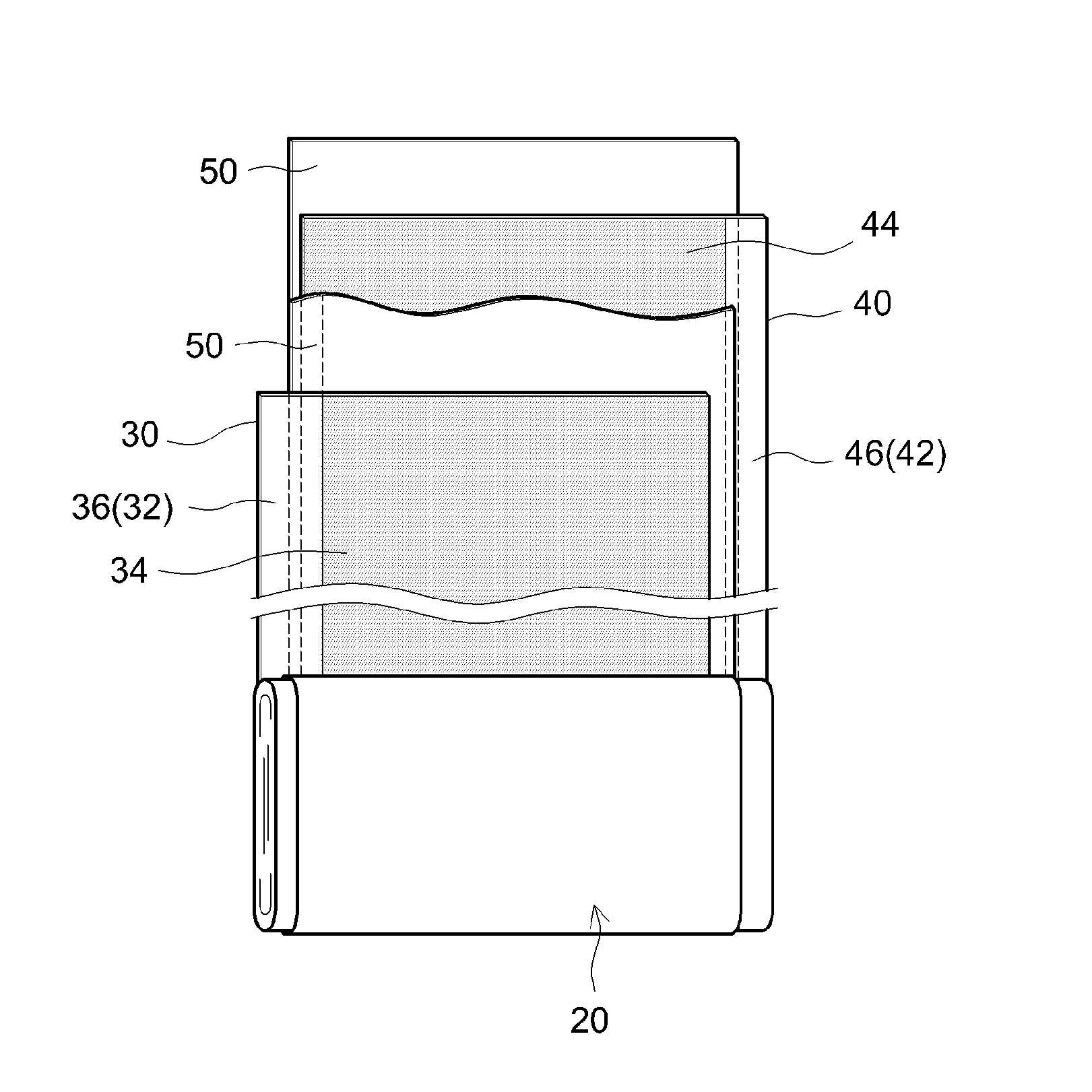
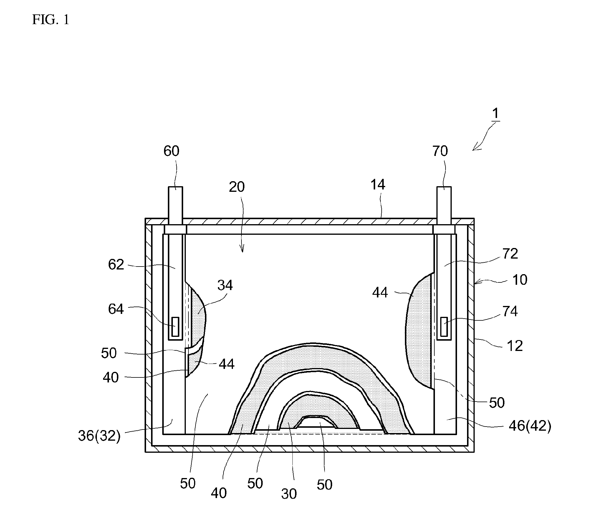
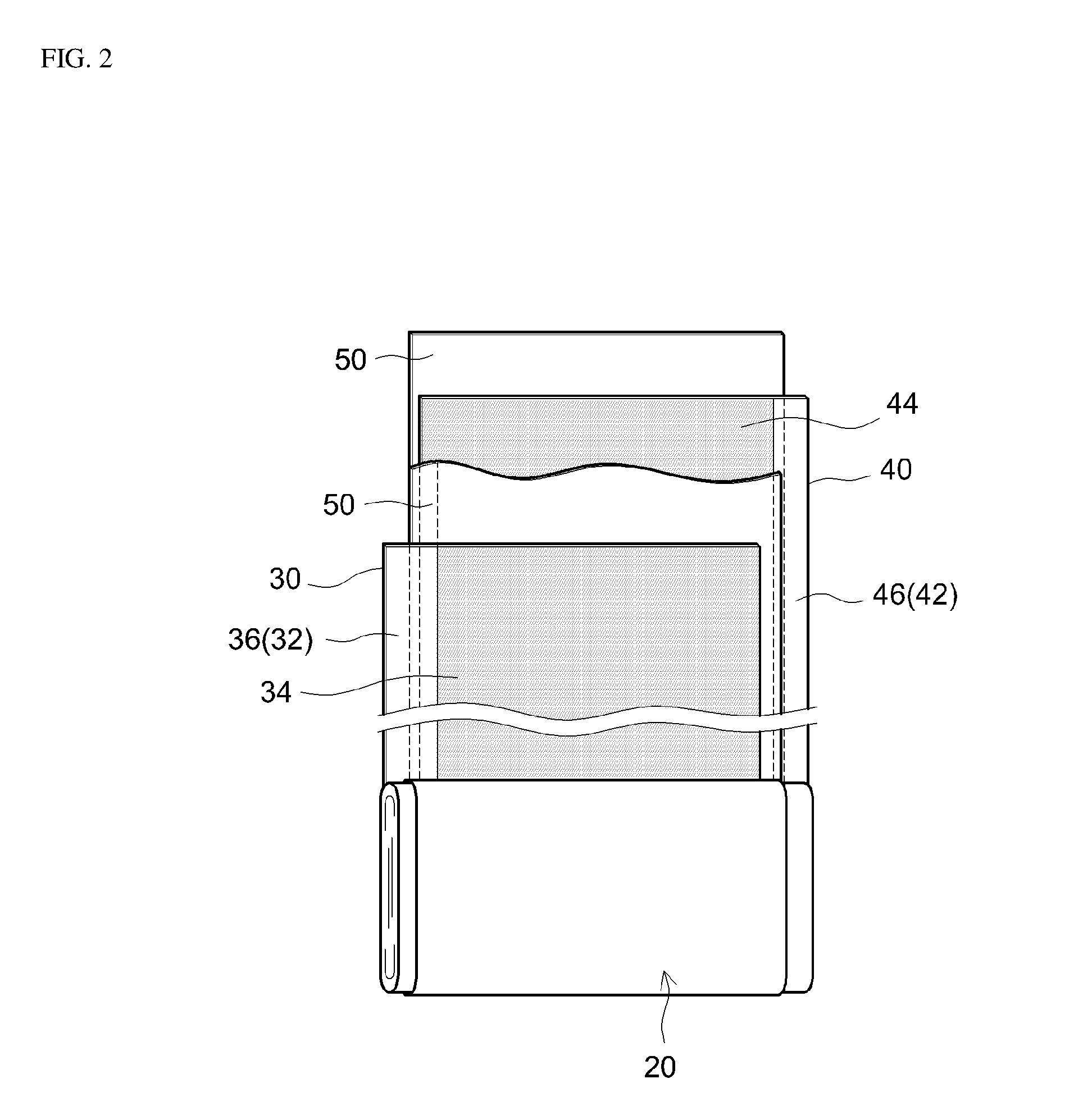
The patent is about a new design for a non-aqueous electrolyte secondary battery that can hold a large amount of electrolyte solution and prevent variations in concentration. It also helps to prevent the battery from overheating and excessive resistance buildup during high rate pulsed charging and discharging. This design improves the battery's durability and performance.

Problems solved by technology

This phenomenon can lead to an increase in resistance during charging and discharging and a deterioration in cycle characteristics during high rate charging and discharging (for example, an increase in resistance caused by high rate charging and discharging), which is not desirable.

Method used


Image

  • Non-aqueous electrolyte secondary battery
  • Non-aqueous electrolyte secondary battery
  • Non-aqueous electrolyte secondary battery

Examples


embodiment 1

Example 1

Construction of Test Lithium Ion Battery

[0072]A lithium-nickel-manganese-cobalt composite oxide having a composition represented by the general formula Li1.14(Ni1 / 3Co1 / 3Mn1 / 3)O2 (NCM, average particle diameter 6 μm) was used as a positive electrode active material. Acetylene black (AB) was used as an electrically conductive material, and poly(vinylidene fluoride) (PVDF) was used as a binder. In addition, a positive electrode active material layer-forming slurry was prepared by weighing out the positive electrode active material, the electrically conductive material and the binder at a NCM:AB:PVDF mass ratio of 93:4:3, adding N-methylpyrrolidone (NMP) so that the solid content concentration (NV) was approximately 50 mass %, and then kneading the obtained mixture in a planetary mixer. Next, a positive electrode sheet was prepared by coating the positive electrode active material layer-forming slurry on both surfaces of a long aluminum foil having a thickness of 15 μm as a pos...

example 2

[0079]A separator having the second resin layer on both surfaces of the separator-based material was prepared by coating the second resin slurry on both surfaces of the separator base used in Example 1. A lithium ion battery of Example 3 was constructed using this separator, with other conditions being similar to those used in Example 1.

example 3

[0080]A lithium ion battery of Example 3 was constructed by reversing the front and back of the separator used in Example 1, with other conditions being similar to those used in Example 1. That is, the battery was constructed by preparing the separator in such a way that the surface of the separator on which the second resin layer was formed faced the positive electrode and the surface of the separator on which the first resin layer was formed faced the negative electrode.


PUM

PropertyMeasurementUnit
Gurley valueaaaaaaaaaa
thicknessaaaaaaaaaa

Abstract

Provided is a non-aqueous electrolyte secondary battery in which an increase in resistance is suppressed when high rate pulsed charging and discharging is repeatedly carried out. The non-aqueous electrolyte secondary battery provided by the present disclosure is provided with: a positive electrode; a negative electrode; a separator; and a non-aqueous electrolyte solution. The separator is provided with a separator base made of a non-woven fabric; a first resin layer provided on a surface of the separator base that faces the positive electrode; and a second resin layer provided on a surface of the separator base that faces the negative electrode. In addition, a resin matrix of the first resin layer is constituted from polytetrafluoroethylene or a copolymer containing polytetrafluoroethylene as a primary component, and a resin matrix of the second resin layer is constituted from poly(vinylidene fluoride) or a copolymer containing poly(vinylidene fluoride) as a primary component.

Description

CROSS-REFERENCE[0001]The present application claims priority on the basis of Japanese Patent Application No. 2015-098038, which was filed on 13 May 2015, and the entire contents of that application are incorporated by reference in the present specification.BACKGROUND OF THE INVENTION[0002]1. Field of the Invention[0003]Embodiments of the present disclosure relate to a non-aqueous electrolyte secondary battery provided with a wound electrode body.[0004]2. Description of the Related Art[0005]Non-aqueous electrolyte secondary batteries such as lithium secondary batteries are lighter and have higher energy densities than existing batteries, and have therefore been used in the past in so-called portable power sources for personal computers, hand-held devices and the like, in power sources for propelling vehicles, and in residential power storage devices and the like. In particular, non-aqueous electrolyte secondary batteries have been advantageously used in recent years as high output po...

Claims


Application Information

Patent Timeline
Patent Type & Authority Applications(United States)
IPC IPC(8): H01M2/16H01M10/0587H01M4/131H01M4/587H01M4/505H01M4/62H01M4/133H01M10/0525H01M4/525H01M50/403H01M50/414H01M50/417H01M50/426H01M50/451H01M50/454H01M50/457H01M50/489H01M50/491
CPCH01M2/1666H01M2220/30H01M10/0587H01M4/131H01M4/525H01M4/505H01M4/625H01M4/623H01M4/133H01M4/587H01M4/622H01M2/162H01M2/1653H01M2004/028H01M2004/027H01M2/145H01M2220/20H01M10/0525H01M50/44H01M50/451H01M50/491H01M50/426H01M50/489H01M50/414H01M50/417H01M50/403H01M50/457H01M50/454H01M4/13Y02E60/10Y02P70/50H01M10/0431H01M50/446H01M50/46H01M50/449H01M50/463Y02T10/70
Inventor UMEYAMA, HIROYAFUKUMOTO, YUSUKEWADA, NAOYUKIYOKOYAMA, YUJIHASHIMOTO, TATSUYAONODERA, NAOTO
Owner TOYOTA JIDOSHA KK
Learn More