
Method and apparatus for secure remote control of power-on state for computers

a remote control and computer technology, applied in the field of remote control of computer systems, can solve the problems of significant higher implementation cost and complexity, lack of flexibility in the solution, and simple ability to power a machine on remotely

Inactive Publication Date: 2006-03-21
HEWLETT PACKARD DEV CO LP
View PDF35 Cites 16 Cited by
  • Summary
  • Abstract
  • Description
  • Claims
  • Application Information

AI Technical Summary

Benefits of technology

[0010]The remote control mechanism of the invention provides flexibility because many different command sequences may be transmitted over the RS-232 connections. The mechanism is secure because each host computer's power-on state is controlled using an independent RS-232 connection rather than by using the LAN; RS-232 connections are not easily accessed by unauthorized users. Moreover, the mechanism is inexpensive because it utilizes RS-232 hardware rather than more expensive LAN hardware. The mechanism may be used to control a single computer or may be scaled to control a large set of computers.

Problems solved by technology

Unfortunately, such solutions lack flexibility: The simple ability to power a machine on remotely is not as useful as the ability to turn it on and off, and to be able to specify the manner in which the machine turns off.
Although other MAC address / LAN techniques have been employed having greater flexibility and features, these more elaborate solutions typically require more than one MAC or IP address per machine.
The use of multiple addresses results in significantly higher implementation cost and complexity.
Moreover, MAC address / LAN techniques lack security: Almost by definition, the use of a LAN means that multiple users will have access to the individual machines that are connected to the LAN.
Therefore, it would be possible for the power-on state of an individual machine to be altered either by mistake or maliciously; either possibility is undesirable.

Method used


Image

  • Method and apparatus for secure remote control of power-on state for computers
  • Method and apparatus for secure remote control of power-on state for computers
  • Method and apparatus for secure remote control of power-on state for computers

Examples


Embodiment Construction

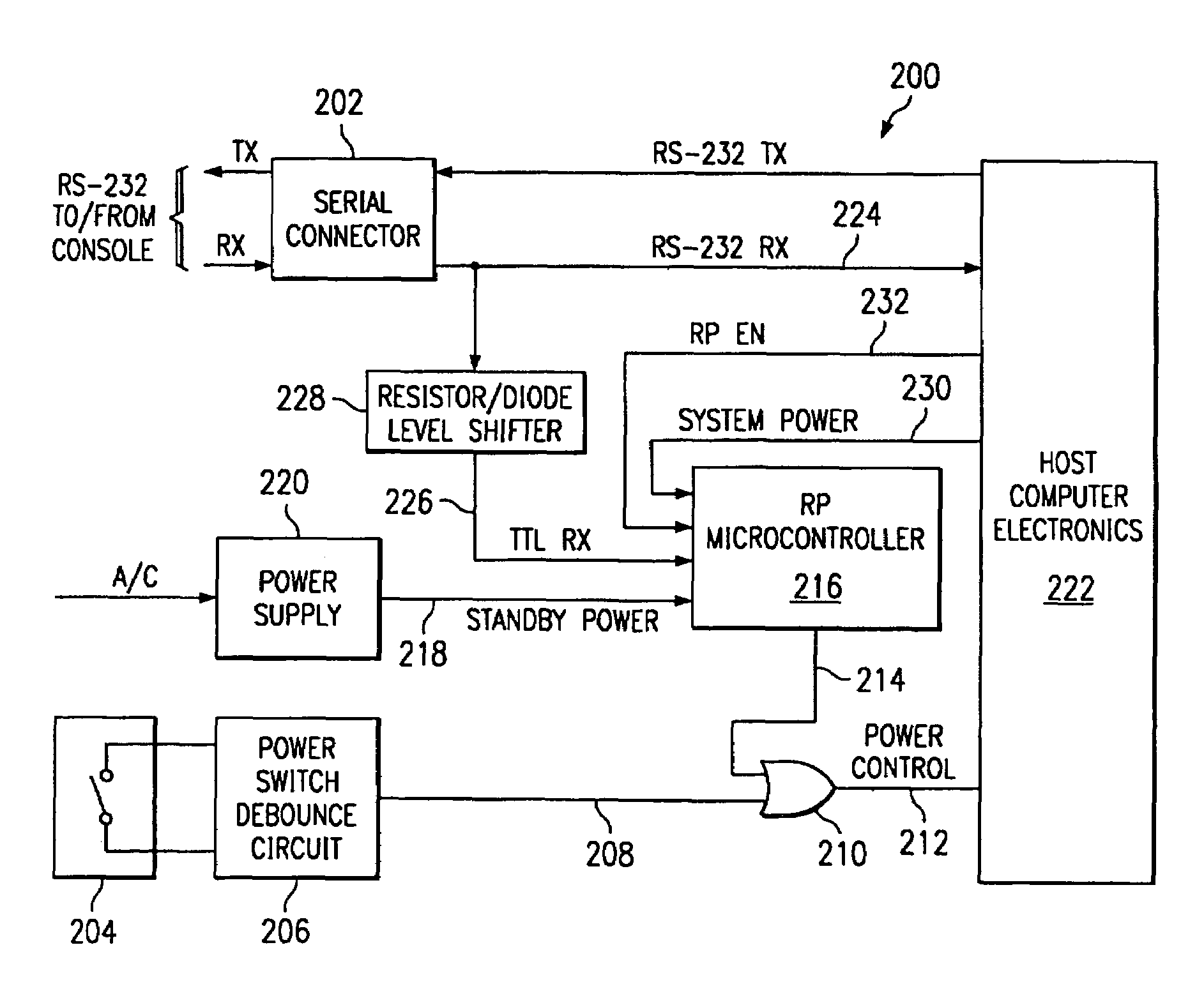
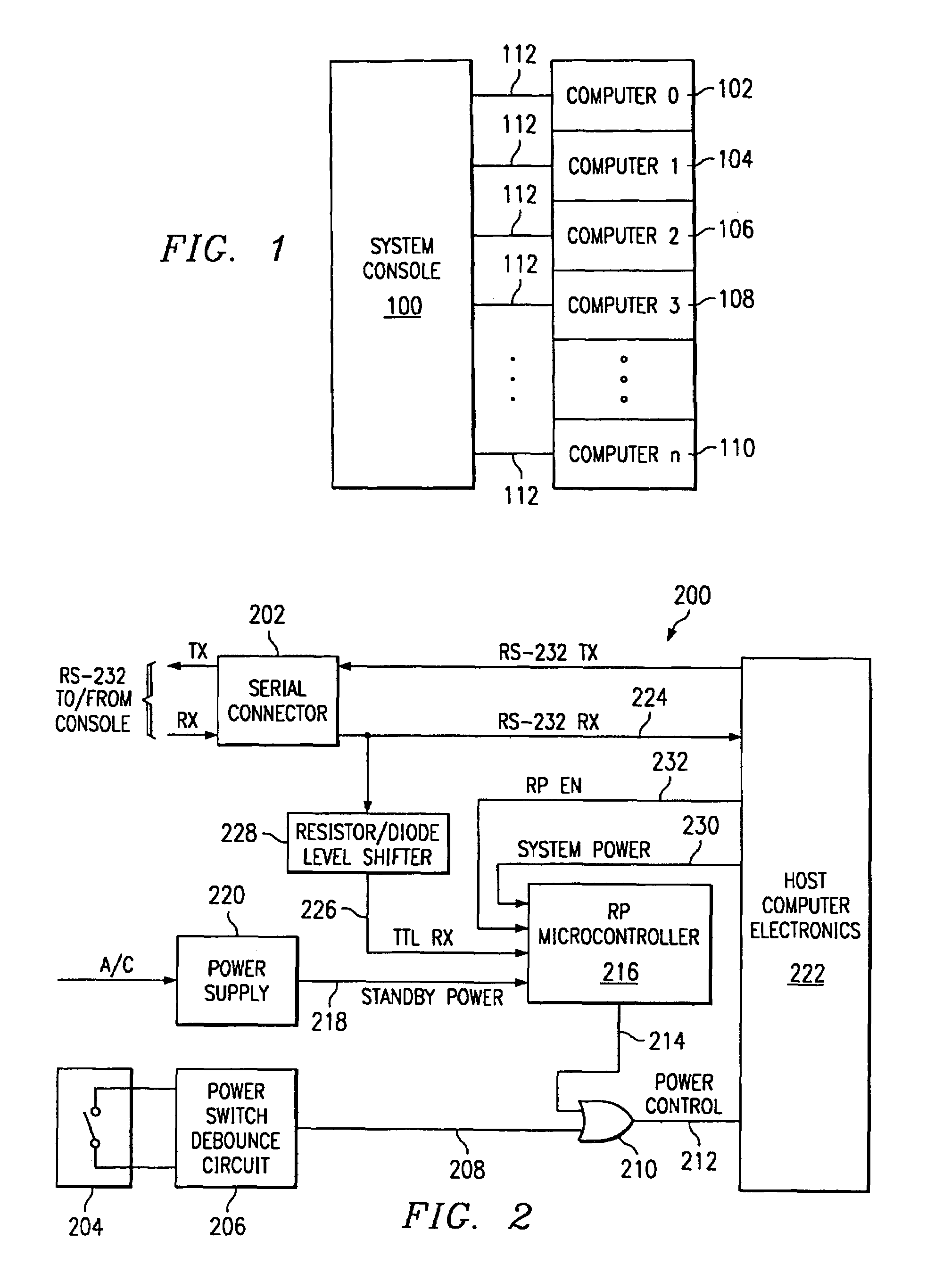
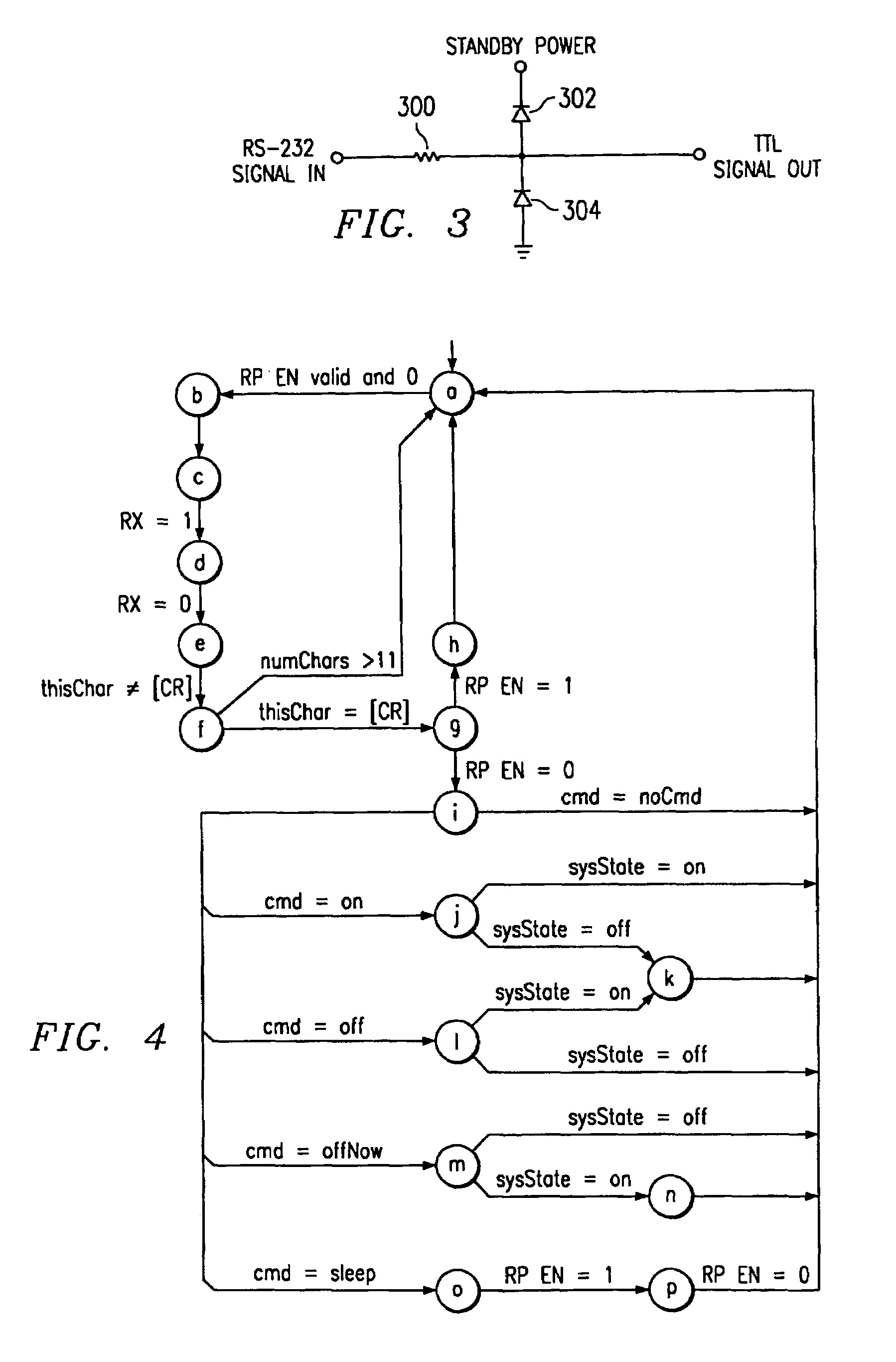
[0015]Structure. Preferred structure for implementing the invention will now be described with reference to FIGS. 1–3.

[0016]FIG. 1 illustrates a system console 100 coupled to multiple remote computers 102–110 with independent RS-232 connections 112 according to a preferred embodiment of the invention. One RS-232 connection is provided for each of the remote computers to be controlled from console 100. Prior art software may be executed on console 100 making the console operable to issue user-typed commands to the remote computers independently over the appropriate RS-232 connections.

[0017]FIG. 2 illustrates a representative one of the multiple remote computers of FIG. 1. Computer 200 has an RS-232 port terminated at serial connector 202. Computer 200 also has a power switch 204 coupled to a power switch debounce circuit 206. Debounce circuit 206 presents a debounced output signal 208 to one of the inputs of OR gate 210. The output of OR gate 210 constitutes a power control signal 21...


PUM


Abstract

A secure mechanism for remotely controlling the power-on state of a host computer: A microcontroller in the host computer is supplied with standby power even when system power to the host computer is turned off. The microcontroller senses the state of the host computer's RS-232 receive line so that commands may be sent to the microcontroller over an RS-232 connection to the host computer. An output of the microcontroller is logically ORed with the output of a power switch debounce circuit of the host computer. The output of the logical OR function is used to manipulate the power-on state of the host computer. The microcontroller may be programmed to respond to numerous commands.

Description

FIELD OF THE INVENTION[0001]This invention relates generally to the remote control of computer systems. More particularly, the invention relates to techniques for remotely controlling the power-on and power-off states of individual computers.BACKGROUND[0002]Multiple individual computers are frequently ganged together for commercial uses of various kinds. For example, network “server farms” commonly include numerous racks of individual computers, each rack populated by several rack-mounted network server computers. In such an environment, it is desirable for a system administrator to be able to control certain functions and states of the individual computers remotely. In particular, it is desirable for a system administrator to be able to remotely control whether an individual computer is powered-on or powered-off.[0003]One prior art method that has been employed to remotely control the power-on state of individual computers has been to use a local area network (“LAN”) connection. Fo...

Claims


Application Information

Patent Timeline
Patent Type & Authority Patents(United States)
IPC IPC(8): G06F1/26G06F1/28G06F1/30
CPCG06F21/57G06F1/26
Inventor LETTANG, FRANK JOHNLEFEBVRE, JOELSCHEID, STEPHEN D.
Owner HEWLETT PACKARD DEV CO LP
Learn More