Methods and systems for remotely controlling a test access port of a target device

a target device and access port technology, applied in the direction of detecting faulty computer hardware, error detection/correction, instruments, etc., can solve the problems of inability to send automatic test equipment, device programmers and trained technicians to the customer, and the inability to configure, verify and test hardware such as the exemplary hardware of fig. 1 and fig. 2

Inactive Publication Date: 2006-03-21
LUCENT TECH INC +1
View PDF5 Cites 33 Cited by
  • Summary
  • Abstract
  • Description
  • Claims
  • Application Information

AI Technical Summary

Benefits of technology

[0020]An exemplary electronic apparatus or target device operative to take advantage of the system and method includes at least one JTAG compliant device. The electronic device is adapted to allow for the JTAG compliant devices and / or interconnections associated therewith, to be at least one of remotely programmed, configured, verified and tested. The electronic apparatus has a JTAG boundary scan chain including the at least one JTAG compliant device, a network interface operative to receive and transmit JTAG messages over a network, and a JTAG driver operative to receive JTAG messages from the network interface, control the boundary scan chain based on the received JTAG messages, and to deliver boundary scan results to the network interface

Problems solved by technology

Programming, configuring, verifying and testing hardware such as the exemplary hardware of FIG. 1 and FIG. 2 can be expensive.
However, these methods become prohibitively expensive once the electronic hardware 302 has been installed in a customer's site.
For example, where an electronic device 302 is installed at a customer's site and requires testing or updating, it can be impractical to send automatic test equipment, device programmers and trained technicians to the customer's site to do the testing or updating.

Method used


Image

  • Methods and systems for remotely controlling a test access port of a target device
  • Methods and systems for remotely controlling a test access port of a target device
  • Methods and systems for remotely controlling a test access port of a target device

Examples


Embodiment Construction

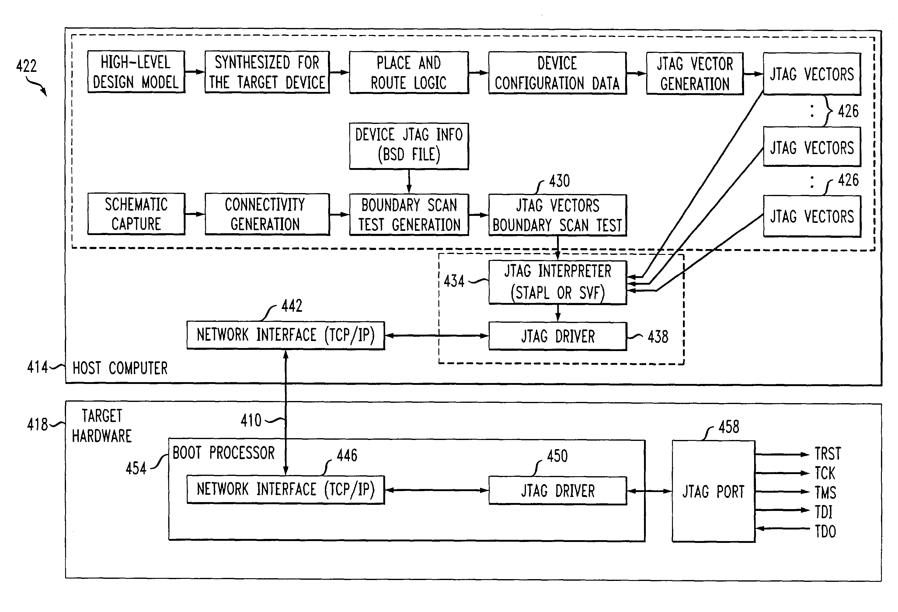
[0031]Referring to FIG. 4, a method of remotely accessing JTAG functionality includes using a network link or connection 410 between a host computer 414 and target hardware 418. For example, the host computer 414 is located at a central product development or product service center. The target hardware 418 is located at a remote customer site. The customer site can be, for example, across the state, across the country or around the world from the location of the host computer 414. The network link 410 can be any kind of network link. For example, the network link 410 can be an Ethernet network, a telephone link, or an Internet connection. The host computer 414 provides many of the same development and testing support functions as the host computer 307 of FIG. 3. However, in the system 422 of FIG. 4, device-specific JTAG vectors 426 and boundary scan test vectors 430 are not delivered to automatic test equipment or device programmers. Instead, these files of programming, configuratio...


PUM


Abstract

JTAG operations are carried out remotely over a network interface. The host processor includes a JTAG interpreter and a host side JTAG driver. A target device includes a target side JTAG driver. The interpreter processes and translates JTAG design files. The host side JTAG driver generates messages for the target side JTAG driver based on the translation. The host JTAG driver delivers the messages to a host network interface. The host network interface is connected via a network link to a target network interface. The target network interface is connected to the target side JTAG driver. The target side JTAG driver communicates with a target boundary scan chain. The target side JTAG driver and host side JTAG driver communicate over the network link. Network overhead is reduced by buffering messages until a message requiring a return of test data is ready for transmission.

Description

FIELD OF THE INVENTION[0001]The invention is directed to a method and system for remotely configuring and testing electronic hardware via an IEEE 1149.1 test access port associated with the electronic hardware.BACKGROUND OF THE INVENTION[0002]The IEEE 1149.1 test access port (TAP) and boundary scan architecture, which is commonly referred to as JTAG, is a popular testing and device programming scheme. JTAG is an acronym standing for the Joint Test Action Group, which is a technical subcommittee that was initially responsible for developing the standard. Many electronic devices are available that comply with the IEEE 1149.1 standard. For example, many Field Programmable Gate Arrays (FPGA), Complex Programmable Logic Devices (CPLD) and memory devices such as Flash and other EEPROM devices include a JTAG Test Access Port (TAP) and can be programmed, configured, tested and verified through the port. Furthermore, the boundary scan architecture provides for the testing of interconnections...

Claims


Application Information

Patent Timeline
Patent Type & Authority Patents(United States)
IPC IPC(8): G06F11/00G01R31/3185G01R31/319G06F11/273
CPCG01R31/318533G06F11/2294G01R31/31907
Inventor GOMEZ, JOSEPH JONAS
Owner LUCENT TECH INC
Why Eureka
Try Eureka