Device for closing and opening the mold halves of a glass molding machine

Inactive Publication Date: 2006-03-28
HEYE HLDG
View PDF9 Cites 22 Cited by
  • Summary
  • Abstract
  • Description
  • Claims
  • Application Information

AI Technical Summary

Benefits of technology

[0006]It is the object of the invention to reduce the spatial requirement of the device inside the frame and to

Problems solved by technology

In this manner, the two piston-cylinder units take up a lot of useful space inside the frame.
Moreover, the linear movement of each piston rod is no longer sufficiently precise and suitably reproducibl

Method used


Image

  • Device for closing and opening the mold halves of a glass molding machine
  • Device for closing and opening the mold halves of a glass molding machine
  • Device for closing and opening the mold halves of a glass molding machine

Examples


Embodiment Construction

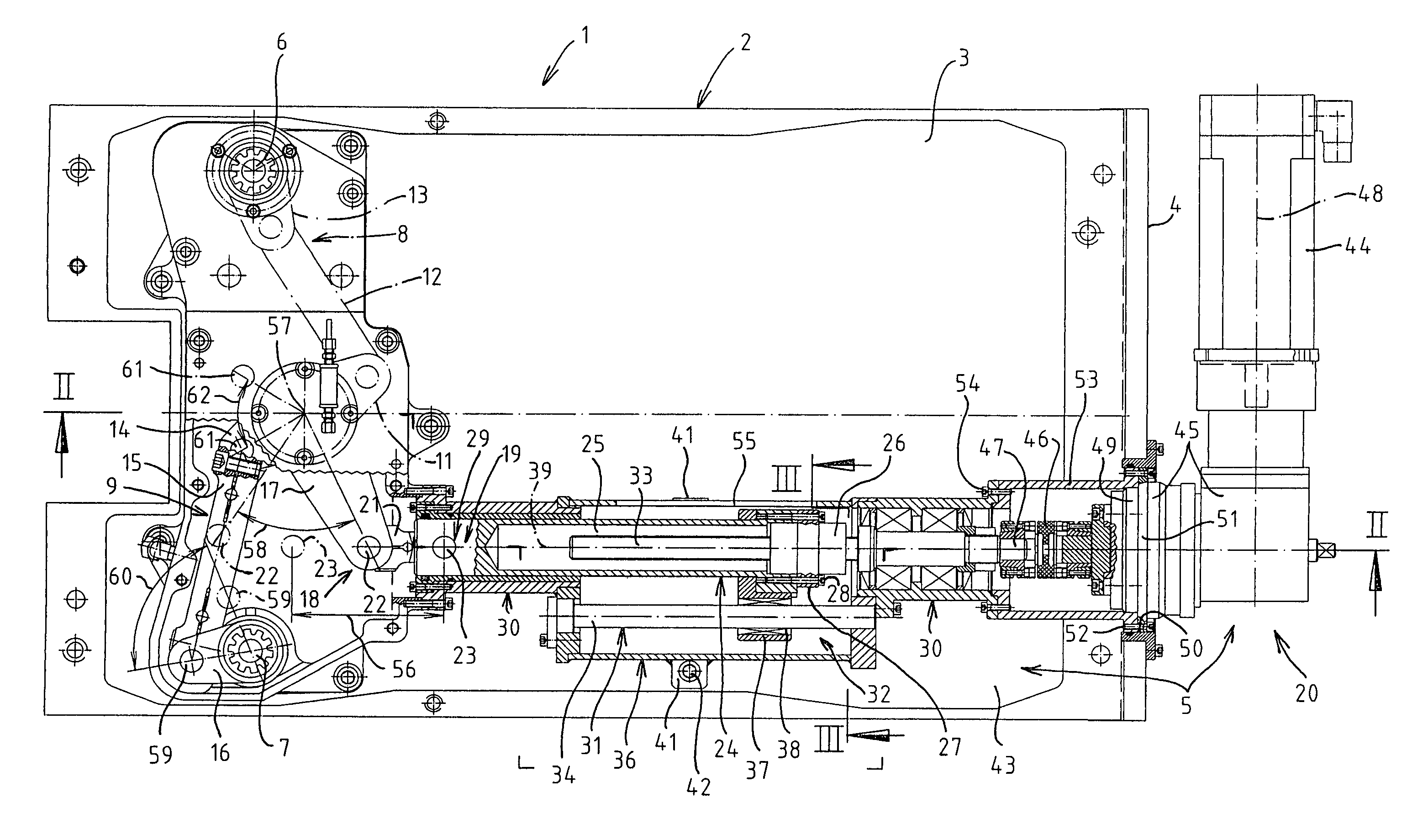
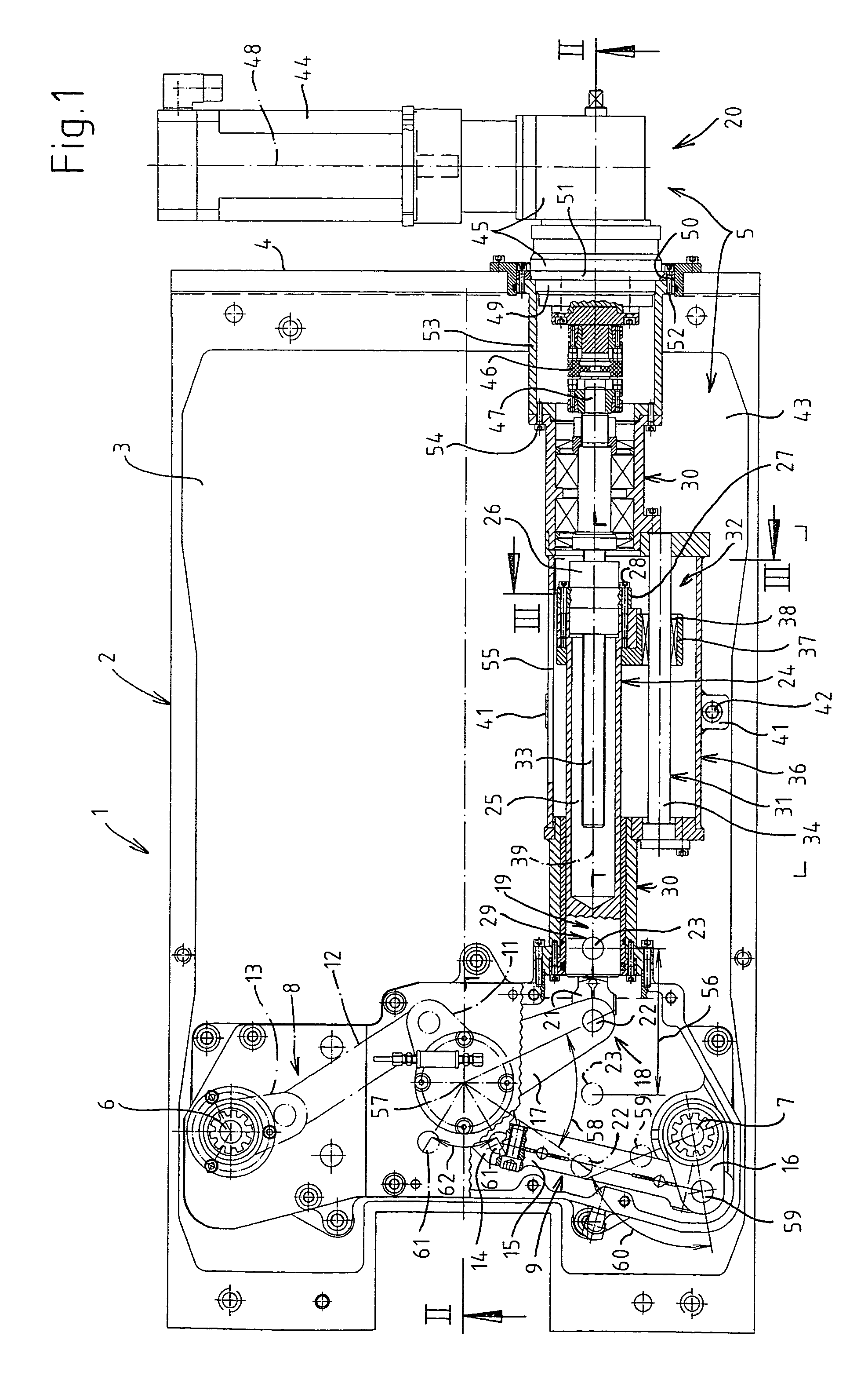
[0021]FIG. 1 shows a part of a glass forming machine 1, in this case a section of an I.S. glass forming machine. The glass forming machine 1 comprises a frame (box) 2 having an internal space 3 and an external wall 4.

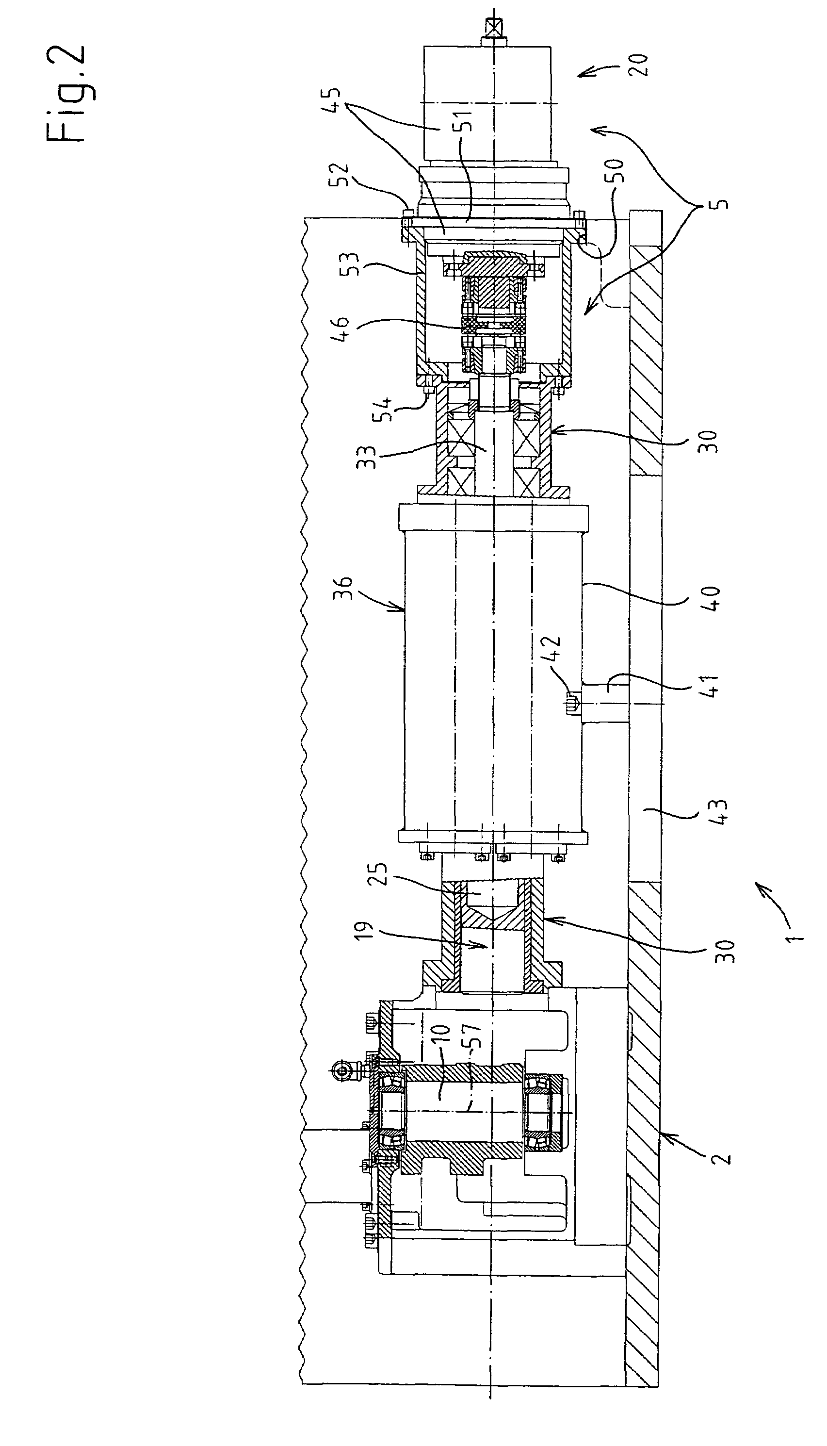
[0022]A device 5 for opening and closing mold halves of at least one mold of the glass forming machine 1 is disposed partially in the internal space 3 and partially outside the frame 2. The mold halves, mold half support mechanisms, hinge column and first intermediate members are known per se e.g. from U.S. Pat. No. 1,911,119A and therefore will not be illustrated and described again here. In the present drawings, the device 5 is intended to close and open finishing mold halves. However, in a similar manner it is also possible to form a device for closing and opening blank mold halves of the glass forming machine 1.

[0023]In the frame 2, vertical shafts 6 and 7 are mounted in a rotatable manner and drive the aforementioned first intermediate members [not illustrated]. Ea...


PUM


Abstract

Each mold half is held by means of a mold half holding mechanism which can be driven so as to pivot in a reciprocating manner about a common vertical hinge column by means of a vertical shaft (6; 7), which is mounted in a rotatable manner in a frame (2) of the glass forming machine (1), and by means of first intermediate members. Each shaft (6; 7) is connected via a lever mechanism (8; 9) to a common drive shaft which can be pivoted in a reciprocating manner by means of a drive element (19), which can be moved linearly in a reciprocating manner, of a drive (20) and by means of second intermediate members (18). The drive element (19) can be mounted on a nut (26) and secured against rotating about a longitudinal axis (39) of the drive element (19) by means of a guide device (32). The nut (26) is in engagement with a spindle (33). The spindle (33) is mounted in an axially fixed, rotatable manner and can be driven rotationally in a reciprocating manner by means of the drive (20).

Description

BACKGROUND OF THE INVENTION[0001]The invention relates to a device for closing and opening mold halves of at least one mold of glass forming machine.[0002]In the case of a known device of this type (U.S. Pat. No. 1,911,119A, FIGS. 3 and 8, or DE 20 27 243 B2, FIG. 3), the devices for closing and opening the blank mold halves and finishing mold halves are formed in a similar manner. In each case, the two intermediate members are driven in a reciprocating manner by means of a piston rod of a piston-cylinder unit. The two piston-cylinder units are disposed in the interior of the frame (box) of the I.S. (individual section) glass forming machine. In this manner, the two piston-cylinder units take up a lot of useful space inside the frame. Moreover, the linear movement of each piston rod is no longer sufficiently precise and suitably reproducible to meet the current requirements for the production of hollow glass.[0003]A parallel closing device for mold halves is known per se from DE 198...

Claims


Application Information

Patent Timeline
IPC IPC(8): C03B9/16C03B9/353
CPCC03B9/165C03B9/3532C03B9/353
Inventor BOGERT, HERMANNDRAWERT, MANFRED
Owner HEYE HLDG
Why Eureka
Try Eureka