Coordinating the functioning of a color control system and a defect detection system for a printing press

a defect detection and color control technology, applied in the field of control system of printing press, can solve the problems of defective color patches, the measurement of color values of defective color patches may not accurately reflect the color within the printed work itself, and the effect of reducing the number of defects

Inactive Publication Date: 2006-03-28
BALDWIN AMERICAS CORP
View PDF43 Cites 51 Cited by
  • Summary
  • Abstract
  • Description
  • Claims
  • Application Information

AI Technical Summary

Problems solved by technology

It is not uncommon for printed images on the web, color patches in particular, to be corrupted by some printing artifact such as the effect of a paper fiber on the blanket roller (commonly known as a hickey), a droplet of ink, an indentation on the blanket, a slime hole in the paper, a scratch on the plate, or some other such defect.
In this case, the measured color values of a defective color patch may not accurately reflect the color within the printed work itself.
While methods for detecting a small defect in a color patch exist in marked color control systems, they are generally limited to eliminating small defects that do not encompass a relatively large portion of the color patch.
However, the color properties of the print work may not remain constant.
However, these systems do not detect defects on the printed work.
Any discrepancy between the acquired image and the template image beyond some tolerance is considered to be a defect.
When the systems detect a large change in color due to a change in inking level, a non-isolated defect is reported over a large portion of the web.
The defect detection control system is not fully functional until a printed product is determined acceptable.
While a template image can be collected before the printed product is considered acceptable, the template image may actually contain a defect, and an actual defective image may be considered acceptable or good, and therefore no corrective action is taken.
Furthermore, the printed product may have subtle defects even when it is judged acceptable.
However, typical defect detection control systems do not allow for a template image that has been collected based on a contract proof, or based on a digital representation of the printed work that was used to create the printing plate.

Method used


Image

  • Coordinating the functioning of a color control system and a defect detection system for a printing press
  • Coordinating the functioning of a color control system and a defect detection system for a printing press
  • Coordinating the functioning of a color control system and a defect detection system for a printing press

Examples


Embodiment Construction

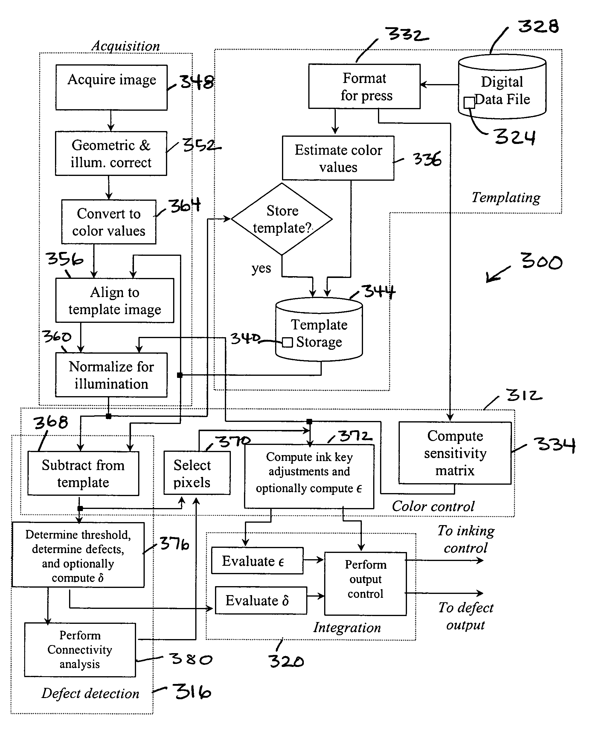
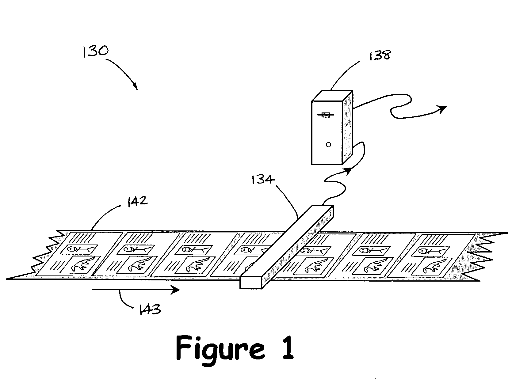
[0027]A control system 130 according to the present invention is shown in FIG. 1. The control system 130 includes a single scanner assembly 134 for both color control and defect detection purposes, and a single system processor 138. The scanner assembly 134 collects image data from a web 142 moving in a direction 143. Once collected, the acquired image data is transferred to the processor 138 for processing in a color control subsystem and a defect detection subsystem. Such processing includes color control, such as ink level adjustment, and defect detection. The ink level adjustment information is then communicated to the associated printing press to effect a change in ink level when deemed necessary as is known in the art.

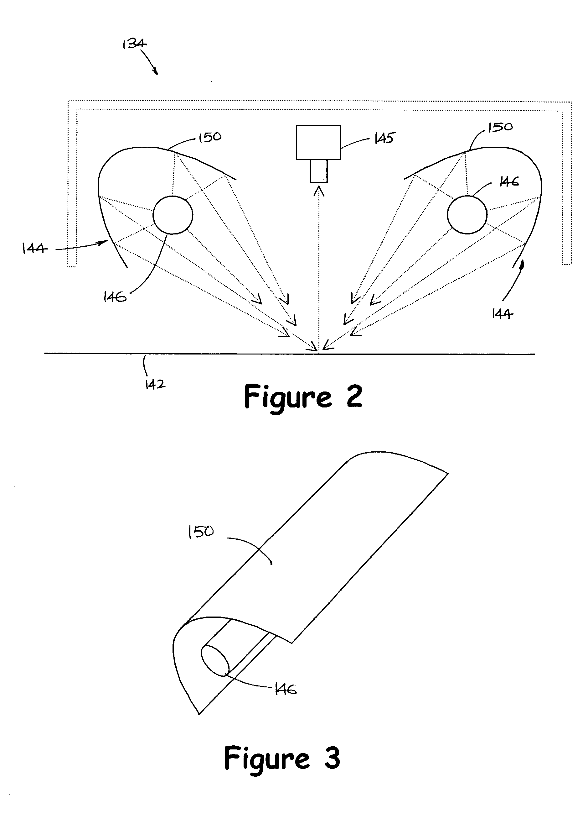
[0028]Generally, the scanner assembly 134 includes a lighting element or a light source which illuminates the moving web 142, an image sensor which senses reflected light from the moving web 142, and any associated optic elements required to appropriately dispers...


PUM


Abstract

A method of coordinating the utilization of a color control system and a defect detection system on a printing press includes acquiring image data and processing the data by a comparison to template image data and the generation of color error data and print defect data. The method further includes the steps of selectively enabling and disabling the color control system and selectively enabling and disabling the defect detection system based upon the color error data and the print defect data.

Description

FIELD OF THE INVENTION[0001]The present invention relates generally to a control system for a printing press, and more particularly, to coordinating the functioning of a color control system and a defect detection system for a printing press.BACKGROUND OF THE INVENTION[0002]A web-offset printing press includes an inking assembly for each color of ink used in the printing process. Each inking assembly includes an ink reservoir and a plurality of hard nylon keys or a segmented blade disposed along the outer surface of an ink fountain roller. The amount of ink supplied to a roller train of the press and ultimately to a substrate, such as a web of paper, is adjusted by changing the spacing between the edge of the blade segments or the nylon keys and the outer surface of the ink fountain roller. The position of each blade segment or each key relative to the ink fountain roller is independently adjustable via an ink control system to thereby control the amount of ink fed to a correspondin...

Claims


Application Information

Patent Timeline
Patent Type & Authority Patents(United States)
IPC IPC(8): B41F1/54B41M1/14G06F15/00G06K9/00B41F31/02B41F33/00B41F33/14G06T1/00
CPCB41F33/0045B41F33/0036
Inventor SEYMOUR, JOHN C.
Owner BALDWIN AMERICAS CORP
Why Eureka
Try Eureka