
Method of changing operating characteristics of an implement

a technology of operating characteristics and implements, applied in the direction of thinning machines, agriculture tools and machines, construction, etc., can solve the problems of increasing the overall cost of the implement, restricting the flexibility of the operation of the work machine,

Inactive Publication Date: 2006-03-28
CATEPILLAR SARL
View PDF28 Cites 59 Cited by
  • Summary
  • Abstract
  • Description
  • Claims
  • Application Information

AI Technical Summary

Benefits of technology

The present invention is a method for changing the operating characteristics of an implement by providing it with a predetermined operational range consisting of multiple values. The implement is connected to a work machine, and an electronic control module is attached to both the work machine and the implement. The electronic control module operates the implement at a first value within the operational range based on a first input signal, and can change from the first value to a second value within the range based on a second input signal. The technical effect of this invention is that it allows for greater flexibility and efficiency in the use of the implement by providing a more customizable range of operating characteristics.

Problems solved by technology

Having an implement with an electronic controller restricts the flexibility of the operation of the work machine by restricting the use of implements with the power machine to only those that have the electronic controller.
Both of these requirements will increase the overall cost of the implement as compared to an implement that does not require the electronic controller to be attached thereto.

Method used


Image

  • Method of changing operating characteristics of an implement
  • Method of changing operating characteristics of an implement
  • Method of changing operating characteristics of an implement

Examples


Embodiment Construction

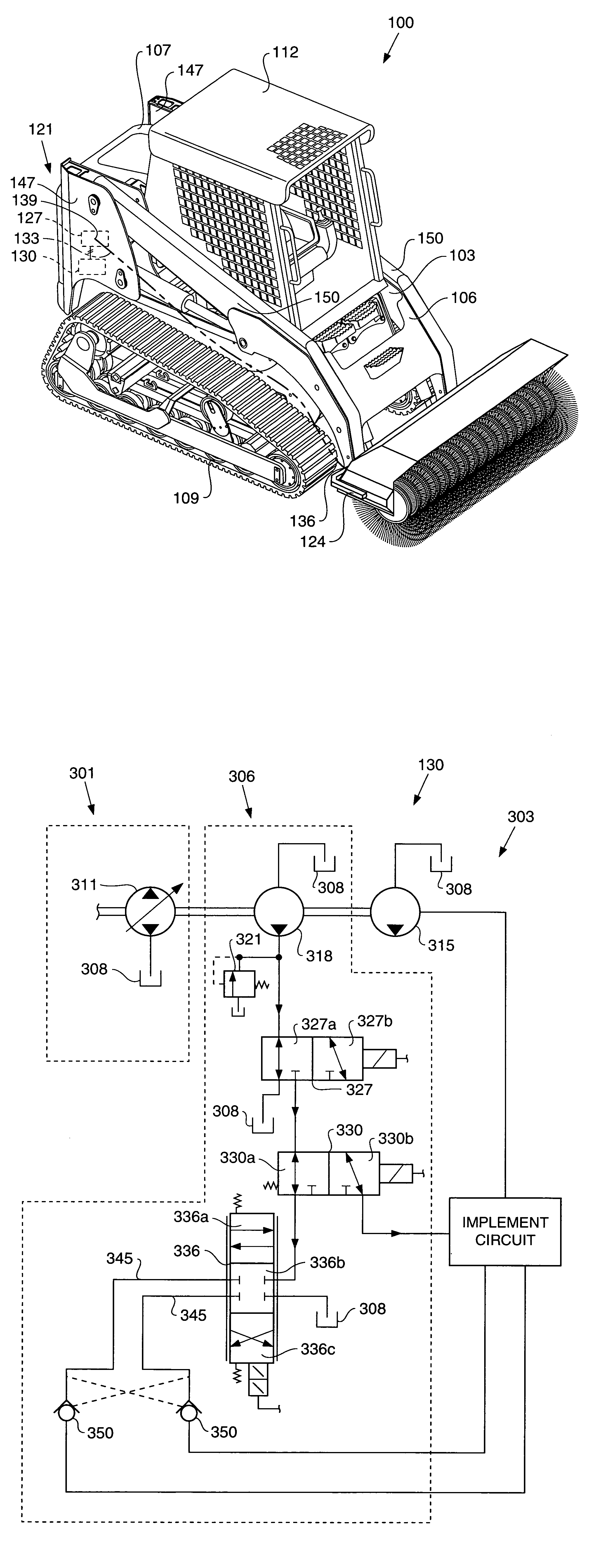
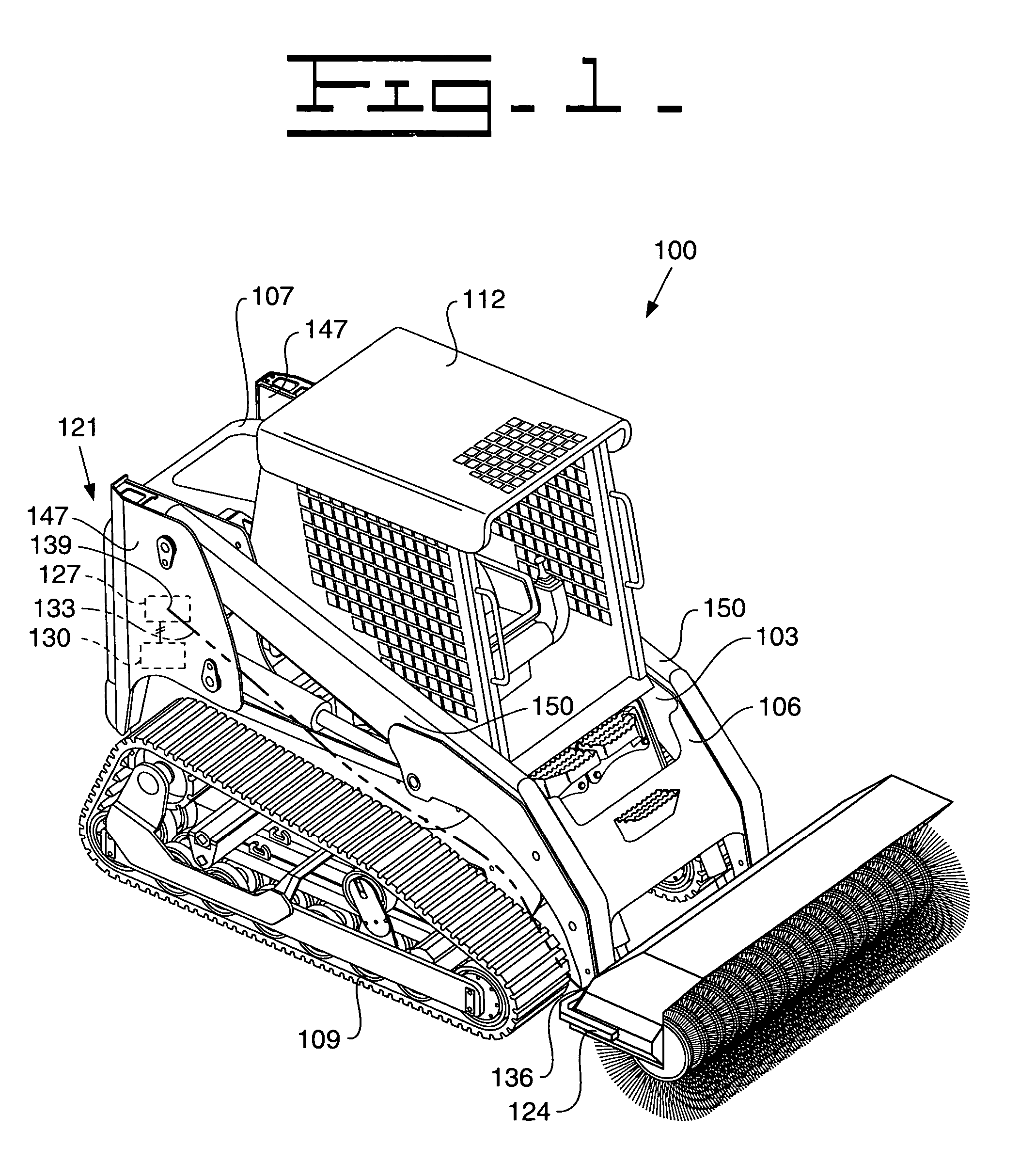
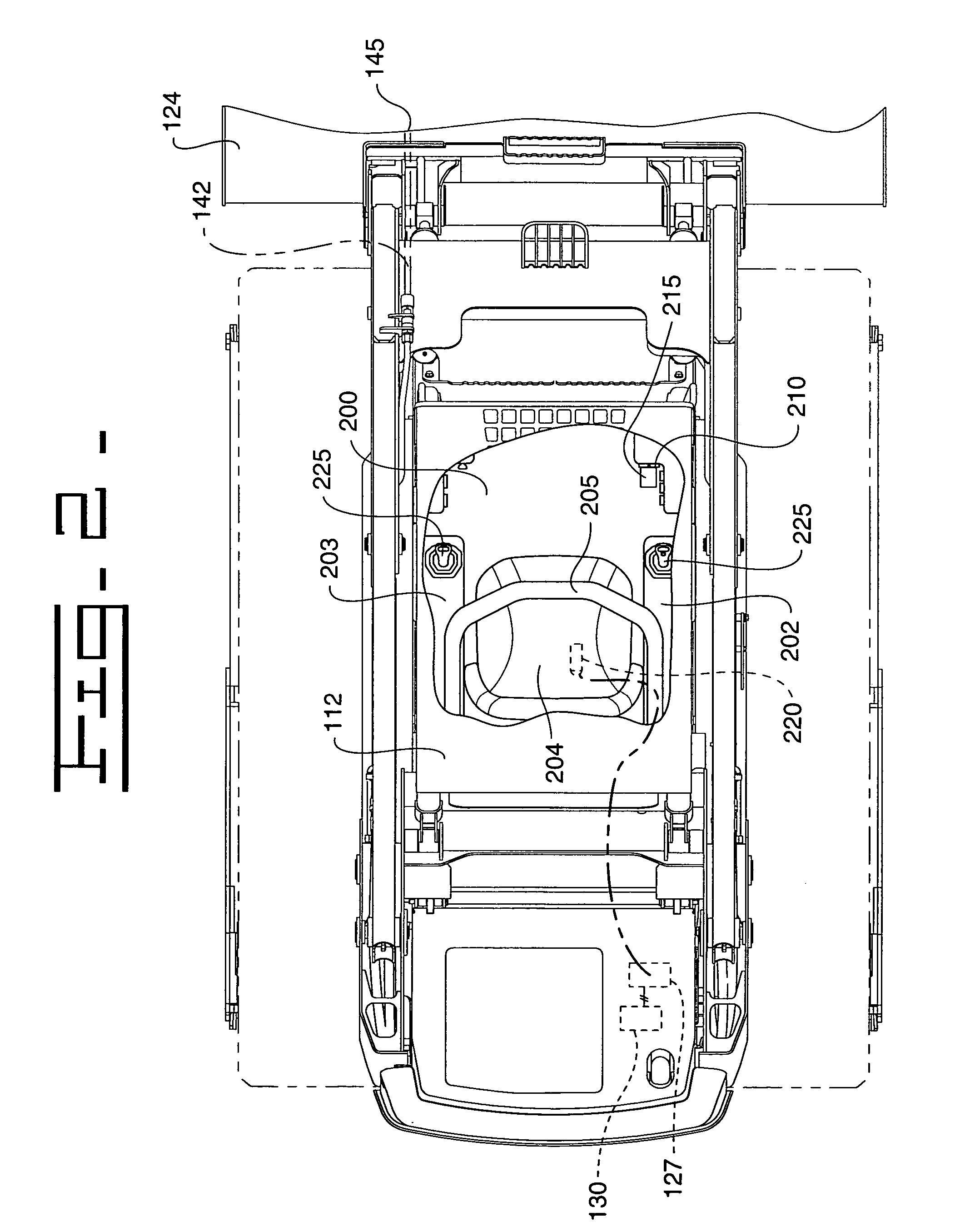
[0011]Referring to the drawings, a method and apparatus for changing operating characteristics of an implement for use with a work machine 100 is shown. With particular reference to FIG. 1, the work machine 100 is depicted as a tracked skid steer loader. It should be understood, however, that the work machine 100 could be any sort of work machine that has hydraulically controlled implements that are removably attached thereto and not just those enumerated above. The work machine 100 has a body portion 103 having a front-end portion 106 and a rear-end portion 107. The work machine includes a plurality of ground engaging support members 109 that support the body portion 103 and an operator's compartment 112 supported on the body portion 103. Further, the work machine 100 includes a lift member assembly 121 pivotally attached to the body portion 106 and an implement 124 pivotally connectable with the lift member assembly 121. The implement 124 has operating characteristics having a pre...


PUM


Abstract

Changing operating characteristics of an implement can expand the capabilities of and enhances the productivity of the implement. The disclosed method and apparatus for changing operating characteristics of an implement comprises, providing the operating characteristics of the implement with a predetermined operational range consisting of a plurality of values, connecting the implement with a work machine, sending a first input signal identifying the operational range to an electronic control module, operating the implement at a first value within the operational range, sending a second input signal relating to a second value within the operational range to the electronic control module, and sending an output signal from the electronic control module to one of the work machine and the implement to change from the first value to the second value.

Description

TECHNICAL FIELD[0001]This invention relates generally to changing operating characteristics of an implement, and, more particularly, to a method and apparatus for identifying the operational range of the operating characteristics of the implement and changing the operating characteristics within the operational range.BACKGROUND[0002]Work machines such as integrated tool carriers, skid steer loaders, backhoe loaders, excavators, and a wide variety of other work machines typically have a plurality of hydraulically controlled implements that may be interchangeably attached to the work machine to perform a particular work function. These implements are normally controlled through an implement control system having one or more hydraulic systems that are used to actuate and control the implement's lift mechanism, tilt mechanism, or auxiliary mechanisms. These implements are likewise controlled through the use of various operator input devices such as one or more implement control levers, ...

Claims


Application Information

Patent Timeline
Patent Type & Authority Patents(United States)
IPC IPC(8): A01B41/06E02F9/20
CPCE02F9/2025
Inventor BELL, JAMES M.SCHENCK, RAYMOND T.DVORAK, PAUL A.SPORER, MARK A.
Owner CATEPILLAR SARL
Learn More