Trigger sprayer spray, off, stream, off indexing nozzle assembly

a technology of indexing nozzle and trigger sprayer, which is applied in the direction of liquid transfer devices, single-unit apparatus, packaging, etc., can solve the problems of liquid leaking the cap is not rotated far enough to position it in the off position, and the liquid is dispersed from the trigger sprayer, etc., to simplify the use of the nozzle cap and enhance the liquid stream configuration.

Active Publication Date: 2006-03-28
WESTROCK DISPENSING SYST
View PDF10 Cites 28 Cited by
  • Summary
  • Abstract
  • Description
  • Claims
  • Application Information

AI Technical Summary

Benefits of technology

[0014]The indexing sprayer nozzle assembly of the present invention overcomes disadvantages associated with prior art nozzle assemblies by providing a cap on the nozzle assembly that can be rotated in either direction to move the cap from an off position to either a spray or stream position. In addition, the cap can be rotated in either direction from the spray or stream position to reposition the nozzle cap in an off position. Still further, the indexing nozzle assembly has a spatial relation between an end surface of the spinner head of the assembly and an interior surface of the nozzle cap that surrounds the discharge orifice of the assembly that improves the stream condition of the liquid discharge.
[0018]The nozzle cap has an end wall that extends across the swirl chamber of the spinner shaft. The discharge orifice passes through the end wall. The end wall has a interior surface that is spaced from the spinner shaft end surface. The spacing of the end wall interior surface from the spinner shaft end surface effectively increases the interior volume of the swirl chamber.
[0020]In use of the indexing nozzle assembly of the invention, with the nozzle cap positioned in the off position on the nozzle base the grooves in the inner cylindrical section of the nozzle cap are not aligned with either the angled channels or the straight channels of the liquid spinner. In this position of the nozzle cap, the trigger sprayer will not dispense liquid on manual manipulation of the trigger. When the nozzle cap is rotated to its spray position, the grooves in the inner cylindrical section of the nozzle cap are aligned with the angled channels of the liquid spinner. This results in liquid being dispensed in a spray pattern when the trigger of the trigger sprayer is manually manipulated. Rotating the nozzle cap to its stream position aligns the grooves in the inner cylindrical section of the nozzle cap with the straight channels of the liquid spinner. This results in liquid being discharged in a stream from the trigger sprayer when the trigger is manually manipulated. Furthermore, the axial spacing between the spinner shaft end surface and the cap end wall interior surface provides an additional volume adjacent the swirl chamber of the liquid spinner that enhances the stream configuration of the liquid dispensed from the trigger sprayer.
[0021]The nozzle cap is mounted to the nozzle base so that the nozzle cap can be rotated in a clockwise or counterclockwise direction to position the cap in any of its off, spray, or stream positions. Furthermore, the axial grooves in the nozzle cap are positioned so that the nozzle cap can be moved to an off condition by one-quarter turn of the nozzle cap in either direction from either its spray position or its stream position, thus simplifying use of the nozzle cap.

Problems solved by technology

Movement of the cap from the off position to one of the spray, stream, or foam positions often requires rotating the cap through an undesired spray, stream, or foam position.
Use of trigger sprayers of this type often results in discharging liquid from the trigger sprayer in a condition that wasn't intended.
Furthermore, when use of the trigger sprayer is finished, the cap at times will not be rotated far enough to position it in the off position.
This could result in the liquid leaking from the trigger sprayer when it is stored if the trigger sprayer should be knocked over onto its side.

Method used


Image

  • Trigger sprayer spray, off, stream, off indexing nozzle assembly
  • Trigger sprayer spray, off, stream, off indexing nozzle assembly
  • Trigger sprayer spray, off, stream, off indexing nozzle assembly

Examples


Embodiment Construction

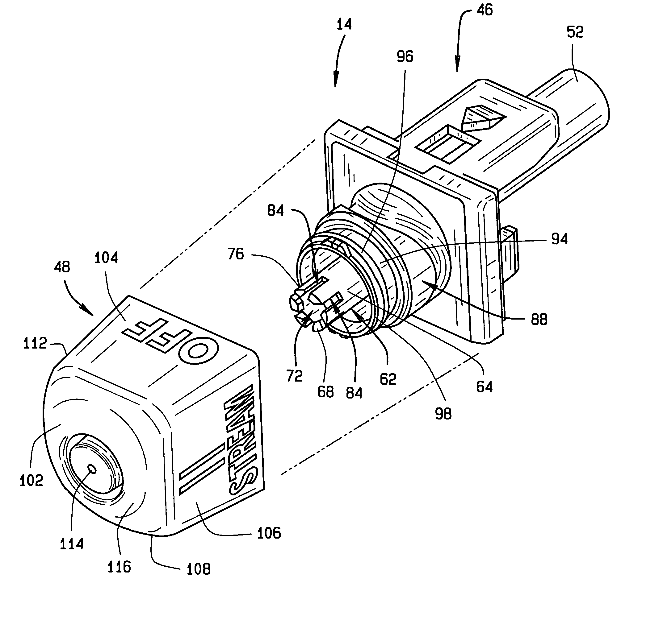
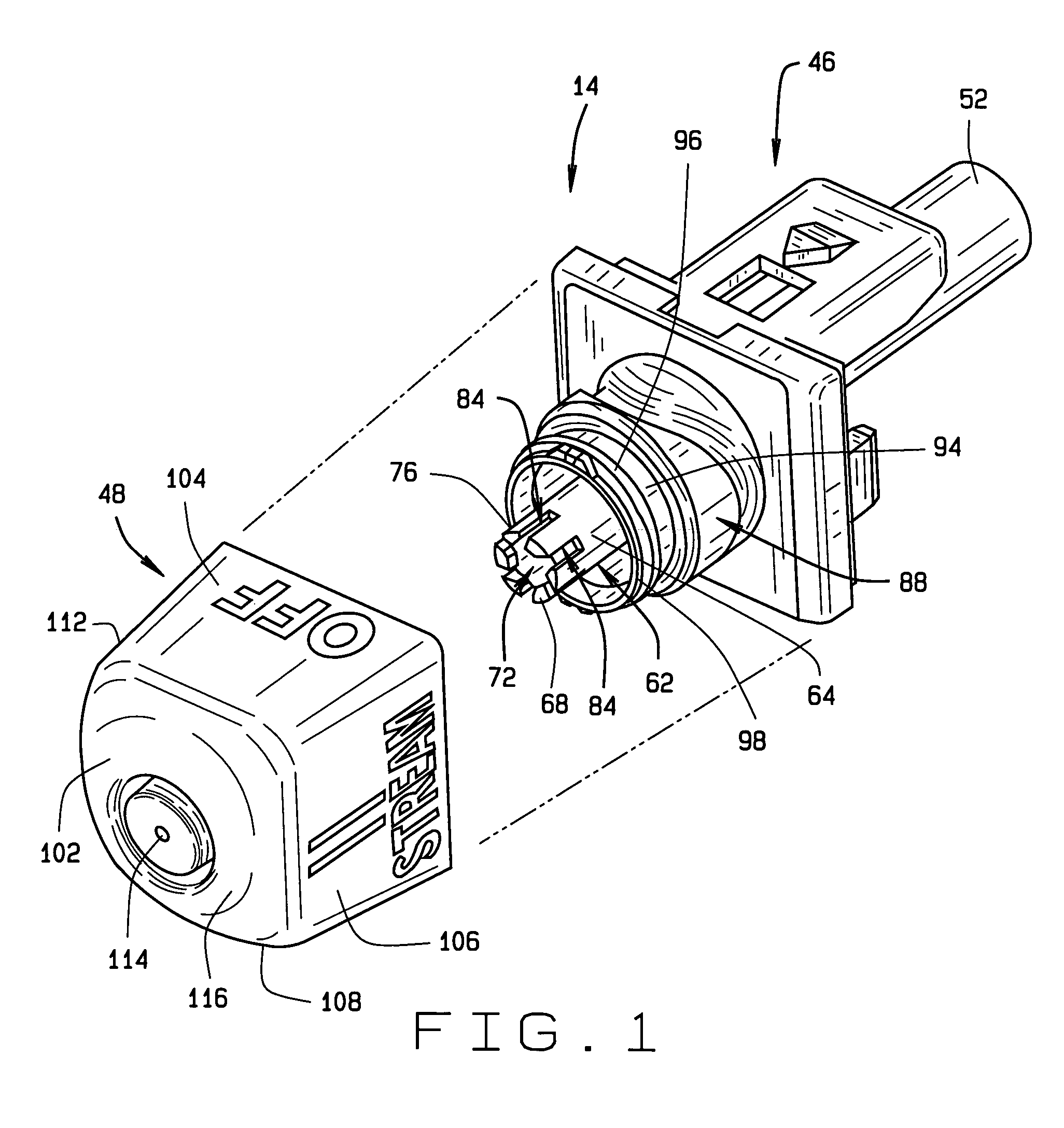
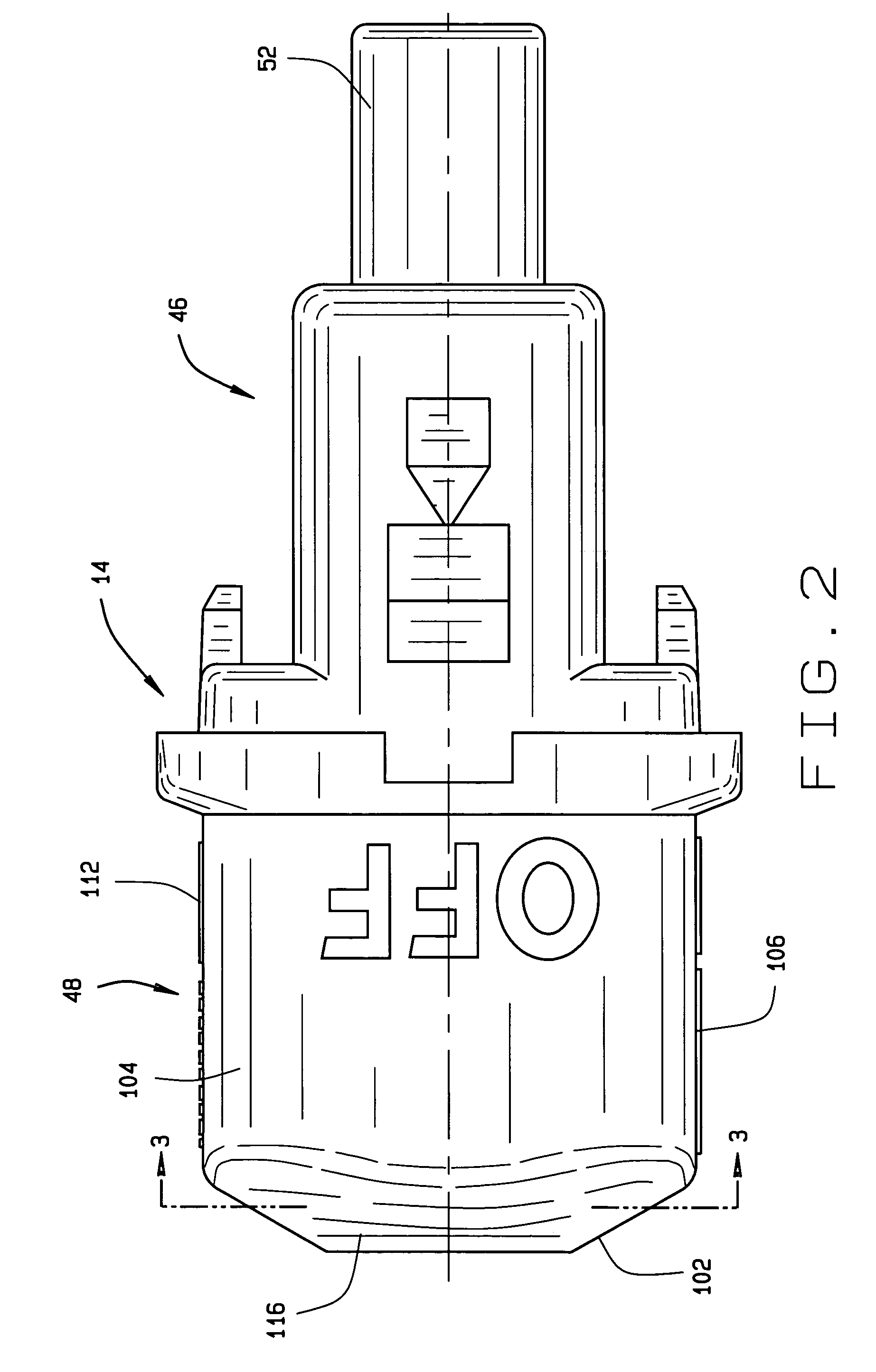
[0030]The trigger sprayer of the present invention is provided with a novel indexing nozzle assembly that can be employed on various different types of trigger sprayers. The indexing nozzle assembly of the invention changes the condition of the liquid discharge of the trigger sprayer between a closed condition, a spray condition, or a stream condition. The unique features of the indexing nozzle assembly can be incorporated into a variety of different types of hand-held and hand-operated trigger sprayers. FIG. 7 shows one example of a trigger sprayer 12 with which the indexing nozzle assembly 14 of the invention may be used. However, it should be understood that the trigger sprayer 12 shown in FIG. 7 is only one example of a trigger sprayer with which the indexing nozzle assembly 14 of the invention may be used. Because the operation of the indexing nozzle assembly 14 does not require any particular trigger sprayer construction, the trigger sprayer 12 of FIG. 7 is described only gene...


PUM


Abstract

An indexing nozzle assembly for a trigger sprayer has a manually rotatable cap mounted for rotation on a liquid spinner of the nozzle assembly. Rotation of a cap changes the nozzle assembly between an off condition, a spray condition, a second off condition, and a stream condition of the liquid discharged from the nozzle assembly. The cap can be rotated from the off position directly to either of the spray or stream positions by rotating the cap one-quarter turn in opposite directions. A spatial relationship between an end surface of the liquid spinner and an interior surface of the cap end wall that surrounds the assembly discharge orifice improves the stream configuration of liquid discharged by the nozzle assembly.

Description

BACKGROUND OF THE INVENTION[0001](1) Field of the Invention[0002]The present invention pertains to a hand-held and hand-operated liquid sprayer typically called a trigger sprayer. In particular, the present invention pertains to an indexing nozzle assembly for a trigger sprayer that has a manually rotatable cap mounted for rotation on a liquid spinner of the nozzle assembly. Rotation of the cap changes the nozzle assembly between an off condition, a spray condition, a second off condition, and a stream condition of liquid discharged from an orifice of the nozzle assembly in one continuous rotation of the cap. In addition, the spatial relationship between an end surface of the liquid spinner and an interior wall of the cap that surrounds the discharge orifice improves the stream configuration of the liquid discharged by the nozzle assembly.[0003](2) Description of the Related Art[0004]Hand-held and hand-operated liquid sprayers commonly known as trigger sprayers are well known in the...

Claims


Application Information

Patent Timeline
Patent Type & Authority Patents(United States)
IPC IPC(8): A62C11/00B05B1/34B05B9/043B67D5/40B05B1/12B05B11/00B67D7/58
CPCB05B1/12B05B11/3011B05B1/3478B05B1/3436B05B11/1011
Inventor FOSTER, DONALD D.
Owner WESTROCK DISPENSING SYST
Why Eureka
Try Eureka